Technical staff manual
-it is necessary to use radiators and circulation pumps of increased power, as the boiler’s heating effect reduces
at using Propylenglycolum (for approximately 10%);
-in the heating system there must be provided a possibility of Propylenglycolum infeed in case of it leakage.
It is necessary to use Propylenglycolum not longer than its shelf life, in accordance with the manufacturers
recommendations.
In the Certificate of boiler’s installation and effectuation of technical service the specialist of the service
organization, that effectuated the boiler’s installation, must make a mark about usage of Propylenglycolum as a
heat carrier, indicating its brand.
7.2.3 New heating system
The new heating system, before connecting it to the boiler must be cleaned from shavings, welding lubrication
burr and other undesirable materials that may have got inside of it at installation, using appropriate means for it.
7.2.4. Existing heating system
The existing heating system must be cleaned from accumulated dirt, rust and scale deposits before connecting
it to the boiler, using appropriate means for it.
7.3.
Selection of an additional expansion tank
The membrane type expansion tank, inbuilt into the boiler is designed for connection of the boiler to the
heating system with a capacity of not more than 70 liters. If the boiler is connected to the heating system with
bigger heat carrier volume, it is necessary to install and additional membrane expansion tank. The additional
expansion tank selection and installation must be effectuated only by a specialized service organization.
Indications on selection of an additional membrane tank are represented in Annex II (page 64).
8.
BOILER INSTALLATION
8.1.
Mounting the boiler to the wall
- The boiler must be installed in kitchens, corridors or other non-living heated premises in accordance with the
gasification project, the set of rules SP 62.13330.2011, SP 41−108−2004, SNiP 41-01-2003 and Regulations of fire
safety of Russian Federation(PPB 01−03);
- in accordance with p. 4.2.7, 4.2.10 and 4.2.11 SP 41−108−2004 the boiler installation should be provided in the
following conditions:
- On the walls made from non-flammable (NG) or low-flammable (G1) materials;
-On the walls covered by non-flammable (RG) or low-flammable (G1) materials (for example roofing steel on a
sheet of heat-insulating layer of non-flammable materials not less than 3 mm thick; lime plaster not less than 10
mm thick) on a distance of not less than 3 cm from the wall. The above mentioned wall covering must get outwards
the boiler’s coating’s dimensions for not less than 10 cm;
-Placing the boiler above the gas stove or kitchen sink is unacceptable;
-In front of the boiler there should be a service zone of not less than 1 meter;
- You should choose a place for installing the boiler taking into account the fact that for convenient service a free
space of not less than 150 mm on the boiler’s lateral sides and not less than 200mm under it is needed. The
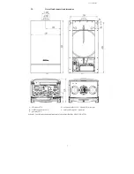
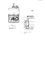
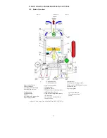
boiler’s overall dimensions are represented on Scheme 1 (page 6);
- Mark the boiler’s attachment points, applying the carrier from the supply package and perforate holes Ø10 mm. In
order to mark the holes on the wall it is recommended to use a harness board, included into the boiler’s supply
package. Put the wall dowels from the supply package into the holes and fix the boiler mounting carrier, using the
screws from the supply package;
-hang the boiler by the mounting holes, located on the channel bars, onto the hooks of the carrier.
8.2
Connecting the boiler to the heating system and the DHW system
- Connecting the boiler to the heating system and the DHW system must be made with metal pipes or flexible
hoses with inner diameter not less than 20 mm for attaching them to the CHand not less than 15 mm for attaching
them to the water supply system. The hoses must be resistant to the inlet water and heat carrier with set parameters
of pressure and temperature. The hoses must be not more that 2,5 meters long. The hoses should be installed in
accordance with the instructions of their manufacturer;
-We strictly recommend to install two stop valves G3/4 by the inlet into the heating system and the output from it
(they are not included into the supply package) in order to effectuate the technical service operations without water
drain from all the heating system;
-In order to avoid boiler’s CH’s dirtying on the heating system’s reverse line (by the inlet into the boiler) it is necessary
to install net filter (“mud flap”) and slime tank;
-A stop valve G1/2 (not included in the supply package) must be installed on the DHW line in front of the filter.
-Remove cover plugs from connection pipes;
-connect the boiler to the heating and water supply systems. Check the joints’ air-tightness.
-Attention! The CH’s pipelines must pass through inner heated premises, otherwise in case of using water as a
heat carrier freezing inside of the CHis possible at sub-zero temperature of surrounding air.
8.3. Connecting the boiler to the gas network
-
In accordance with p. 7 SP 62.13330.2011, the connection of the gas line to the boiler should be made with metal
pipes (steel and copper) and heatproof multi-layered polymer pipes, including also one metal layer (metallopolymeric
pipes). It is acceptable to use multi-layered metallopolymeric pipes for inner gas pipelines at natural gas provision to
one-flat domestic buildings not higher than 3 floors in condition if they are confirmed as acceptable for construction
use. It is acceptable to connect the boiler to the gas pipeline by a flexible tubing (hose), resistant to transported gas at
set pressure and temperature. The inner diameter of pipes and hoses must be not less than 20 mm.
- In accordance with p. 5.5 SP 41−108−2004 the flexible connections shall be not longer than 1,5 m. The
hoses must be installed in accordance with the instructions of their manufacturer.
- Remove cover plugs from connection pipes;
-Install the gas filter and stop valve on the gas pipeline by the inlet into the boiler;
-The gas valve must me easily accessible;
-Connect the boiler to the gas pipeline. Check that there are no gas leakages. Air-tightness control is
effectuated by means of a soap solution bubble test on the joints or by other safe methods. Appearance of
bubbles means that there is a gas leakage. The gas leakage is unacceptable.
8.4. Connecting the boiler to the liquefied gas cylinder
-Before connecting the boiler to the liquefied gas cylinder make sure that your boiler is set up for operation with
this type of gas. Otherwise it is necessary to effectuate the boiler’s rendering to liquefied gas in accordance with
section 12 (page 26).
-The balloon with liquefied gas must necessarily be equipped with a reduction unit with vapor phase stabilization
pressure of 2,9kPa and vapor phase capacity not less than 1 m
3
/hour.
ATTENTION! Using reduction units with stabilization pressure different from 2,9 kPa IS PROHIBITED.
-The hose length for connecting the boiler must be not more than 1,5 m., the inner diameter- not less than
20 mm. The gas supply hose must be resistant to the supplied gas at set pressure and temperature. The
hoses should be installed in accordance with the instructions of their manufacturer.
-In front of the boiler’s inlet a stop gas valve must be installed, which must be easily accessible.
Summary of Contents for NEVALUX-8230
Page 35: ...Assembly is performed in reverse order Scheme 23 Heat exchanger dismantling...
Page 41: ...48...
Page 47: ...Ignition and ionization plugs in the assembly pos 67...
Page 54: ......
Page 55: ......


