Technical staff manual
3.
USER’S MANUAL
3.1.
Control Panel
The main control element of the boiler is the electronic board which controls all boiler’s operation. The
electronic board’s microprocessor collects and processes signals from the control and safety sensors. All
information about the boiler’s condition is displayed on the LCD display in real-time operation mode.
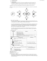
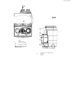
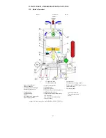
All control over the boiler is effectuated from the control panel, the appearance of which is shown on
Scheme 3.
If a remote control is connected to the boiler, then control is effectuated from it, the buttons of the control panel
are inactive.
In the left part of the control panel there is a pressure gauge, indicating the pressure inside the heating circuit.
Heat carrier pressure in the CHmust be not lower than 1 bar (with pressure lower than 0,5 bar the safety system
will be switched on and it would be impossible to put the boiler into operation).
In the center of the control panel there is an LCD display, showing the temperature in currently active mode at
normal operation of the boiler (at operation in the heating mode it shows the heat carrier temperature in the
heating system by the outlet from the boiler, at operation in the DHW mode –the DHW temperature by the
outlet from the boiler). In case of failure the error code appears on the display instead of temperature. The
boiler’s error codes are represented in the p.14.1 (page 34).
The symbols on display show the boiler’s operation mode. Around the display there are 6 boiler control
buttons. The designation of the control buttons and of the symbols shown on display are represented in the
tables 2 and 3 respectively.
3.2.
Boiler operation modes
The boiler can operate in the following modes:
-
Standby mode (see p. 3.2.1);
-
DHW mode (see p. 3.2.2);
-
combined mode
(see p. 3.2.3, page 10);
-
heating mode (see p. 3.2.4, page 10);
When the boiler is connected to the power line, it automatically sets up to the mode in which it was before
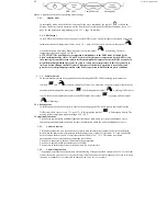
being switched off from the power line. Change of boiler’s operating modes is effectuated by pressing the K5
button on the boiler’s control panel (see p. 3.1, page 8). The sequence of the boiler’s operating modes change is
represented on Scheme 4.
Scheme 3. Boiler’s control panel
Control buttons purpose ________________________________________________________________ Table 2
Designation
Function
K1
DHW temperature increase
K2
DHW temperature reduction
K3
Heating temperature increase
K4
Heating temperature reduction
K5
Choosing the boiler’s operation mode, switching the boiler on/off (see p. 3.2)
K6
Reset of the boiler’s electronic board blocks (RESET)
Purpose of symbols shown on display ______________________________________________________ Table 3
Symbol
Is always glowing
Flickering
Antifreeze function operating symbol (see p. 3.3.1,
page 10)
Presence of flame on the burner
Standby mode
Boiler in the DHW standby mode
Boiler operating in the DHW mode
Boiler in the heating standby mode
Boiler operating in the heating mode
RESET
Error code, reset request
Error code, maintenance service required
Parameters programming (see p. 13.3.1, page 30)
Parameter number displayed
Parameter value displayed
Remote control connected
Remote control connection error
Summary of Contents for NEVALUX-8230
Page 35: ...Assembly is performed in reverse order Scheme 23 Heat exchanger dismantling...
Page 41: ...48...
Page 47: ...Ignition and ionization plugs in the assembly pos 67...
Page 54: ......
Page 55: ......


