6
STARTUP
33
www. matrix-vision.com
BVS SC-_1280Z00-30-0-0
SMART
CAMERA
Fieldbus
www.balluff.com
6.6 Digital I/O interface
The
SMARTCAMERA
provides eight internal I/O signals. Depending on the variant, they
are connected with the signals at the plug connectors. The digital I/O 2 to 5 are not di-
rectly connected with physical outputs.
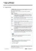
Digital inputs and outputs are configured in the System settings on the Digital in-
puts/outputs tab.
Setting
Description
I/O type
Defines whether it is an input, an output, the flash line or the trigger line.
Inputs can be read using the "
Get inputs
" tool. Outputs can be set using
the "
Set outputs
" tool. Advanced settings regarding the flash and trigger
can be made in the "
Set up camera
" tool.
Name
A user defined name to describe this configuration which can be used in the
above mentioned tools to address this In-/Output.
I/O de-
vice
Hardware device which is used for this In-/Output. ( e.g. the active camera)
Line
Hardware line of the device which is used for this In-/Output.
Inv.
If activated the in/output gets inverted. Inverted in/outputs are interpreted as
active on low voltage.
LED
If activated, the state of the in/output is shown with the camera LED. (only
supported on smart cameras)
Duration
Defines the pulse duration of an output in milliseconds. The default value of
0 means, that the output is active until another value is set manually using
the "
Set outputs
" tool. Choosing pulse durations larger than zero the out-
put is active for the defined time span and retransferred into its inactive
state afterwards.
Delay
Defines the delay of the trigger or an output in milliseconds. The default
value of 0 means, that the trigger will start without delay or rather will the
output toggle when the tool "
Set outputs
" is running. Choosing delay larger
then zero the frame acquisition will be delayed or rather the output will be
delayed with respect to the of frame acquisition.
NOTE
After switching on and after switching to another inspection pro-
gram the outputs are set as in the general settings:
•
0 V if Inv. is not active
•
24 V if Inv. is active
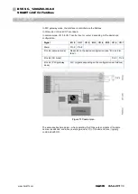
The logical signals I/O 0 and I/O 1 are permanently linked with the physical signals of the
power connection. I/O 0 to I/O 7, on the other hand, can be output at the IO-Link connec-
tion depending on the configuration.
Three options are supported (see “Camera mode”).
NOTE
If the pulse length exceeds the throughput time for an inspection
this may result in undesired effects.


