


6
STARTUP
34
www. matrix-vision.com
BVS SC-_1280Z00-30-0-0
SMART
CAMERA
Fieldbus
www.balluff.com
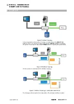
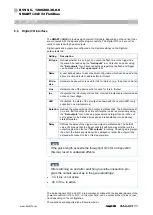
In PLC gateway mode, the interface is controlled via the fieldbus.
In I/O mode, I/O 6 and I/O 7 are linked.
In camera mode, I/O 0 to I/O 7 can be input or output, depending on the device and
configuration.
Signal
I/O 0
I/O 1
I/O 2 I/O 3 I/O 4 I/O 5 I/O 6
I/O 7
Power
Pin 2 Pin 4
I/O-Link (camera mode)
Depends on the device configuration (see “IO-Link inter-
face”).
I/O-Link (I/O mode)
Pin 2 Pin 4
I/O-Link (PLC gateway
mode)
N.C. (signals depending on the configuration via fieldbus)
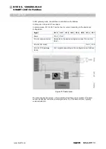
Figure 13 Control plan
The same applies here again
– when operating the I/O as output, signals of the same
name are switched, and when operating as input, I/O of the same name or logically
combined with OR.