


6
STARTUP
51
www. matrix-vision.com
BVS SC-_1280Z00-30-0-0
SMART
CAMERA
Fieldbus
www.balluff.com
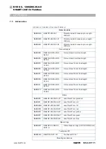
Config Assembly
All camera functions are set via the Web interface. The configuration data include only
IO-Link functions.
Start byte
Length
Description
0
2
IO-Link port function
0: Standard-I/O, 1: IO-Link
2
1
Cycle time
Bit 0-5: Multiplier
Bit 6-7: Time base
3
1
Validation Type
0: no validation, 1: compatible (VID, DID),
2: identical (VID, DID, serial number)
4
2
Vendor ID
6
3
Device ID
9
16
Serial Number
25
1
Parameter Server
Bit 0: Enable upload
Bit 1: Enable download
Bit 6: Delete
Bit 7: Enable parameter server
IO-Link port function
This parameter determines whether pin 4 works in IO-Link mode (1) or whether it is used
as a digital in-/output (0). Pin 2 is always a digital in-/output.
There is no setting that specifies whether a pin is an input or output. A digital I/O pin is
always both. If a pin is to be used as an input, the output must output a zero (byte 128 in
the output assembly). The output stage is a “highside switch”, and if it outputs a zero, the
pin is highimpedence and can be used as an input. The input data (byte 128 in the input
assembly) always represent the logical value of the corresponding pin, even if it is con-
trolled as an output.
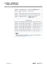
Cycle time
This parameter can be used to influence the IO-Link communication speed. The time for
an IO-Link process data cycle results from the time base and the multiplier.
Since the multiplier takes up 6 bits, it can have values from 0 to 63.
The time base is 2 bits which are coded as follows.
Binary coding
Base time
Calculation
Time range
00
0.1 ms
Multiplier x base time
0.4
1)
…63 ms
01
0.4 ms
6.4 ms + multiplier x base time
6.4…316 ms
10
1.6 ms
32 ms + multiplier x base time
32…1328 ms
1)
0.4 ms is the shortest possible cycle time. It can also not be fallen below using a
smaller multiplier.