6
STARTUP
28
www. matrix-vision.com
BVS SC-_1280Z00-30-0-0
SMART
CAMERA
Fieldbus
www.balluff.com
5. Copy the update file (BVS_Cockpit_X.X.X.sh) to the updates folder. The
SMARTCAMERA
will now automatically start the update process. This may take up
to 5 minutes. The Power LED on the front side will flash red during the update. The
SMARTCAMERA
is inaccessible in the network during the update.
ATTENTION
Never disconnect the camera from power during an update.
This can result in irreparable damage to the
SMARTCAM-
ERA
.
6. After a few minutes the update will be finished and the Power LED will change to
green. The
SMARTCAMERA
is now ready for use.
6.2 Network topologies
For the startup of the
SMARTCAMERA
, it is first integrated in the network environment.
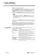
The different options are described in the following examples. This covers a large part of
the application cases. To operate the
SMARTCAMERA
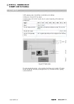
requires that the supply voltage
is provided via the power connection in any case.
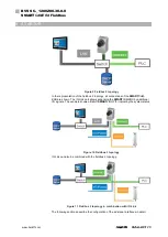
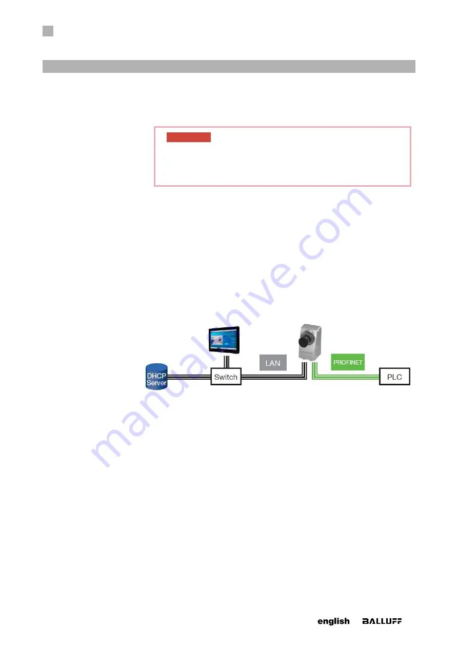
In the fieldbus 1 topology, both network connections of the
SMARTCAMERA
are being
used. The LAN connection is used for the configuration and, if necessary the monitoring
during operation. The communication for the controller runs via PROFINET or Ether-
Net/IP.
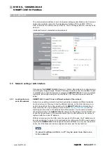
To reduce the wiring effort, the system can also be operated as in fieldbus 2 topology.
Only the PROFINET port is used in this case. The real-time communication for the con-
trol as well as the configuration via the web interface are possible at the same time via
this port. Because of the prioritization of the PROFINET communication and the lower
transfer rate, this may lead to performance constraints of the web interface.


