69
deutsch
69
E
19 18 17 16 15 14 13 12 11 10 9 8 7 6 5 4 3 2 1
X5
Head 1
Head 2
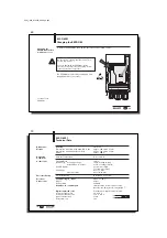
Changing the
EEPROM in the BIS
C-6001 processor
Location of the
EEPROM
BIS C-6001
Changing the EEPROM
To replace the EEPROM, open up the processor as described on 61.
Be sure before opening that the unit is discon-
nected from power.
To avoid damaging the EEPROM, please
observe the requirements for handling electro-
statically sensitive components.
The EEPROM is replaced by unplugging and
plugging back into the socket.
C60_1-023_819395_0508_en.p65
70
70
E
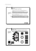
Dimensions,
Weight
Housing
Plastic PS
Dimensions with read/write head BIS C-652
approx. 169 x 90 x 35 mm
Dimensions with adapter BIS C-650
approx. 184 x 90 x 35 mm
Weight
approx. 400 g
Ambient Temperature
0 °C to +60 °C
Terminal Block
19-pin
Cable Entry
for supply voltage
1 x PG 9 fitting (metal)
for I
NTER
B
US
, in-/output
2 x PG 11 fittings (metal)
Cable Diameter
4 to 8 mm for PG 9
5 to 10 mm for PG 11
Wire gauge
0.14 to 1 mm
2
with end crimps
0.25 to 0.34 mm
2
Enclosure Rating
IP 65 (when connected)
Supply Voltage V
S
, input
DC 24 V ± 20 %
Ripple
≤
10 %
Current Draw
≤
400 mA
I
NTER
B
US
, In-/ and Outputs
serial interface for remote bus station,
Ident-No. 03, 16 bytes IN, 16 bytes OUT
Digital Input (+IN, –IN)
Terminal block, Optocoupler isolated
Control voltage active
4 V to 40 V
Control voltage inactive
1.5 V to –40 V
Input current at 24 V
11 mA
Delay time, typ.
5 ms
BIS C-6001
Technical Data
Operating
Conditions
Connections
Enclosure Rating
Electrical
Connections


