background image

71

71

deutsch

D

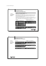
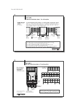
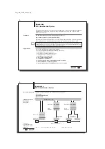
Service-Schnittstelle

RS 232

Schreib-/Lesekopf*

integriert, BIS C-65_ und folgende;

alternativ bei montiertem Adapter BIS C-650*

2 x Einbaustecker 4-polig (Stift)
für alle Schreib-/Leseköpfe BIS C-3_ _
mit 4-poligem Stecker (Buchse),
nicht BIS C-350 und BIS C-352

alternativ bei montiertem Adapter BIS C-670*

1 Einbaustecker 8-polig (Stift) für die
Schreib-/Leseköpfe BIS C-350 / BIS C-352

BIS-Betriebszustände

LED rot / grün

Ready / Bus active

(LED im Gehäuse)

LED grün / gelb

CT1 Present / Operating

LED grün / gelb

CT2 Present / Operating

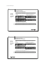
Zustand I

NTER

B

US

LED grün

Reset

(LED seitlich

LED grün

Cable Check

am Gehäuse)

LED grün

Bus active

LED gelb

Remotebus Disable

Elektrische
Anschlüsse

(Fortsetzung)

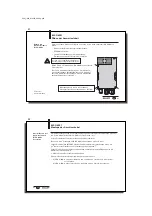
BIS C-6001
Technische Daten

Funktionsanzeigen

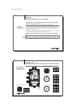
Mit dem CE-Zeichen bestätigen wir, dass unsere Produkte den Anforderungen
der EG-Richtlinie

89/336/EWG (EMV-Richtlinie)

und des EMV-Gesetzes entsprechen. In unserem EMV-Labor, das von der DATech für
Prüfungen der elektromagnetischen Verträglichkeit akkreditiert ist, wurde der Nachweis
erbracht, dass die Balluff-Produkte die EMV-Anforderungen der Fachgrundnorm

EN 61000-6-4 (Emission), EN 61000-4-2/3/4/5/6 (Störfestigkeit) erfüllen.

* um ± 90° umsetzbar

C60_1-023_819395_0508_d.p65

72

72

D

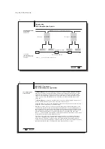
Balluff Identifikations-System

Baureihe C Schreib-/Lesesystem

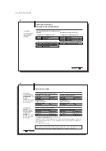
Hardware-Typ
6001 = I

NTER

B

US

 (Fernbus)

Software-Typ
023 = I

NTER

B

US

Schreib-/Lesekopf
000 = ohne Schreib-/Lesekopf
651 = Schreib-/Lesekopf Typ 651 (mit Rundantenne stirnseitig)
652 = Schreib-/Lesekopf Typ 652 (mit Rundantenne frontseitig)
653 = Schreib-/Lesekopf Typ 653 (mit Stabantenne)
650 = Adapter mit zwei Anschlüssen für externe Schreib-/Leseköpfe BIS C-3_ _

(ausgenommen BIS C-350 und BIS C-352)

670 = Adapter mit einem abgesetztem Anschlussstecker für

einen externen Schreib-/Lesekopf BIS C-350 oder BIS C-352

Schnittstelle
Bus-Varianten

Kundenanschluss
KL2 Klemmenanschluss über 1 x PG 9 und 2 x PG 11

Typenschlüssel

BIS C-6001
Bestellinformationen

BIS C-6001-023-_ _ _-03-KL2

Summary of Contents for BIS C-60 1

Page 1: ...English please turn over C60_1 023_819395_0508_d p65 2 Nr 819 395 D E Ausgabe 0508 nderungen vorbehalten Ersetzt Ausgabe 0506 Balluff GmbH Schurwaldstra e 9 73765 Neuhausen a d F Deutschland Telefon...

Page 2: ...im industriellen Bereich entsprechend Klasse A des EMV Gesetzes eingesetzt werden Installation und Betrieb sind nur durch geschultes Fachpersonal zul ssig Unbefugte Eingriffe und unsachgem e Verwendun...

Page 3: ...ird Einige der wesentlichen Einsatzgebiete finden sich in der Produktion zur Steuerung des Materialflusses z B bei variantenspezifischen Prozessen beim Werkst cktransport mit F rderanlagen zur Datenge...

Page 4: ...teeinheiten BIS C 60_1 verf gen zus tzlich ber einen digitalen Eingang Der Eingang hat je nach Konfiguration unterschiedliche Funktionen siehe Konfiguration Welche der oben beschriebenen Anordnungen b...

Page 5: ..._0508_d p65 10 10 D INTERBUS Die Kommunikation zwischen der Auswerteeinheit BIS C 60_1 und dem steuernden System erfolgt ber den INTERBUS Das INTERBUS System besteht aus drei Komponenten der Anschaltb...

Page 6: ...itialisierung ber cksichtigt aber dem Anwender nicht mitgeteilt BUS Anbindung INTERBUS C60_1 023_819395_0508_d p65 12 12 D 1 2 3 Kompatibilit t zur Auswerteeinheit BIS C 6_1 Kompatibilit t einstellen...

Page 7: ...t setzt sie ein Bit AE Bit 5 Hat die Steuerung alle wichtigen Daten bernommen signalsiert sie dies der Auswerte einheit durch R cksetzen des am Beginn gesetzten Bit AV Bit 6 Die Auswerteeinheit setzt...

Page 8: ...puffers f r einen 1 Schreib Lesekopf Funktionsbeschreibung Ausgangspuffer Belegung und Erkl rung Sub Bit Bedeutung Funktionsbeschreibung adresse name 00Hex CT Datentr gertyp Datentr gertyp ausw hlen f...

Page 9: ...inzipiellen Ablauf auf den 13 und 28 35 und die Beispiele auf den 36 55 C60_1 023_819395_0508_d p65 18 18 D Erkl rungen zum Ausgangspuffer Fortsetzung Sub Bedeutung Funktionsbeschreibung adresse 02Hex...

Page 10: ...Datentr ger Fortsetzung siehe n chste Erkl rungen zum Ausgangspuffer Fortsetzung Funktionsbeschreibung Ausgangspuffer Belegung und Erkl rung Bitte beachten Sie den prinzipiellen Ablauf auf den 13 und...

Page 11: ...b Bit Bedeutung Funktionsbeschreibung adresse name 00Hex Fortsetzung Bitleiste IN Input Wenn der Parameter Eingang IN 1 ist zeigt dieses Bit den Zustand des Eingangs an AF Auftrag Fehler Der Auftrag w...

Page 12: ...auf den 13 und 28 35 und die Beispiele auf den 36 55 C60_1 023_819395_0508_d p65 24 24 D Sub Bedeutung Funktionsbeschreibung adresse 02Hex Konfiguration 2 Byte 80Hex Defaultwert Werkseinstellung Diese...

Page 13: ...heit an IN 0 digitaler Eingang low IN 1 digitaler Eingang high Reset der Auswerteeinheit BIS C 60_1 ber den digitalen Eingang Ist diese Funktion aktiviert wird ein Reset der Auswerteeinheit durchgef h...

Page 14: ...olgenden Ablauf siehe Beispiele auf den 38 46 1 Die Steuerung gibt auf den Ausgangspuffer die Befehlskennung an Subadresse 01Hex die Anfangsadresse ab der gelesen geschrieben werden soll an Subadresse...

Page 15: ...60_1 abgelehnt wenn sich kein Datentr ger im aktiven Bereich des Schreib Lesekopfs befindet Ist die Funktion Dynamikbetrieb konfiguriert nimmt die Auswerteeinheit den Lese Schreibauftrag an und speic...

Page 16: ...reibauftrag verwendet Dieser wird mit einer Fehlermeldung abgelehnt wenn die Auswerteeinheit erkennt dass der Datentr ger nicht den richtigen CRC enth lt Datentr ger ab Werksauslieferung alle Daten si...

Page 17: ...Befehlskennung und Programmnummer Die einzelnen Programms tze m ssen l ckenlos aneinander anschlie en Sie m ssen nacheinan der bergeben und mit 2 Byte FFHex FFHex als Endekennung abgeschlossen werden...

Page 18: ...32 Byte Blockgr e Da 2 Byte je Block f r den CRC verwendet werden sind lediglich 120 Byte des Datentr gers f r die Nutzbyte verf gbar Somit Anfangsadresse 0 Anzahl Byte 120 Steuerung 1 Subadressen de...

Page 19: ...rung 1 Subadressen des Ausgangspuffers in der Reihenfolge der Darstellung bearbeiten 3 Subadressen des Eingangspuffers bearbeiten 7 Subadressen des Eingangspuffers bearbeiten 5 Subadressen des Eingang...

Page 20: ...kgr e AV Bit setzen 00Hex 07Hex AA Bit setzen 01 06Hex Die ersten 6 Byte Daten eintragen 00Hex 07Hex TO Bit invertieren 00Hex 07Hex AE Bit setzen 01 06Hex Die zweiten 6 Byte Daten eintragen 00Hex 07He...

Page 21: ...olge der Darstellung bearbeiten Identifikations System BIS C 60_1 2 Subadressen des Eingangspuffers in der Reihen folge der Darstellung bearbeiten Wenn Fehler sofort eintritt 3 Subadressen des Ausgang...

Page 22: ...essen des Eingangspuffers bearbeiten Funktionsbeschreibung Beispiele f r den Protokollablauf C60_1 023_819395_0508_d p65 44 44 D Schreiben von 16 Byte ab Datentr geradresse 20 Datentr gertyp mit 32 By...

Page 23: ...Hex 00Hex 07Hex CT Bit auf 0 32 Byte Blockgr e AV Bit setzen 00Hex 07Hex AA Bit setzen 01 06Hex Die ersten 6 Byte Daten eintragen 00Hex 07Hex TO Bit invertieren 01 06Hex Die zweiten 6 Byte Daten eintr...

Page 24: ...pelter Bitleiste Abspeichern eines Programms f r das Auslesen von 3 Datens tzen 1 Datensatz Anfangsadresse 5 Anzahl Byte 7 2 Datensatz Anfangsadresse 75 Anzahl Byte 3 3 Datensatz Anfangsadresse 312 An...

Page 25: ...le nicht verwendeten Anfangsadressen und Anzahl Byte mit FFHex f llen Fortsetzung siehe n chste C60_1 023_819395_0508_d p65 50 50 D 00Hex 07Hex AV Bit r cksetzen 00Hex 07Hex AA Bit und AE Bit r cksetz...

Page 26: ...Beispiel 2 auf 38 W hrend der Gemischte Datenzugriff abgearbeitet wird ist der Dynamikbetrieb ausgeschaltet C60_1 023_819395_0508_d p65 52 52 D 12 Beispiel Gemischter Datenzugriff Bei Konfiguration mi...

Page 27: ...mieren Das Programmieren von Konfigurationsdaten ist in beiden Puffern f r Kopf 1 und Kopf 2 m glich Steuerung 1 Subadressen des Ausgangspuffers in der Reihenfolge der Darstellung bearbeiten Identifik...

Page 28: ...em der Datentr ger erkannt wurde Andernfalls m ssen f r den Energieaufbau bis zum Erkennen des Datentr gers 45 ms hinzugerechnet werden F r zweimaliges Lesen und Vergleichen Datentr ger mit 32 Byte je...

Page 29: ...819395_0508_d p65 58 58 D ber die drei seitlichen LED meldet die Auswerteeinheit BIS C 60_1 die wichtigsten Betriebszust nde des Identifikations Systems Betriebszustand LED Bedeutung Ready Bus active...

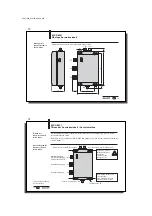
Page 30: ...UL CC BA RD Funktionsanzeigen C60_1 023_819395_0508_d p65 60 60 D Anordnung des Schreib Lesekopfes bzw des Adapters BIS C 6001 Montage Kopf Auswerteeinheit Je nach Ausf hrung ist die Auswerteeinheit...

Page 31: ...ugsdrehmoment 0 15 Nm C60_1 023_819395_0508_d p65 62 62 D BIS C 6001 Montage der Anschlusskabel Um die Betriebsspannung den digitalen Eingang und die INTERBUS Verbindungen herzustel len ist die Auswer...

Page 32: ...uf der Klemmleiste die Anschl sse 1 5 f r die Eingangsschnittstelle und die Anschl sse 8 12 f r die Ausgangsschnittstelle des INTERBUS Die folgende Zeichnung gibt die Verkabe lung wieder wenn die Ausw...

Page 33: ...m ssen paarweise verdrillt sein Empfohlener Kabeltyp LiYCY 3x2x0 25 mm2 maximale Kabelkapazit t 120 pF m Schirm leitend mit Stecker geh use ver binden Adern verdrillt3 Klemmleiste der Eingangs schnitt...

Page 34: ...dass der Schirm eine einwandfreie Verbindung zum PG Geh use hat Bitte Einbauanleitung auf 63 beachten C60_1 023_819395_0508_d p65 68 68 D Anschluss f r Schreib Lesekopf 8 polig BIS C 6001 Schnittstell...

Page 35: ...169 x 90 x 35 mm Abmessungen mit Adapter BIS C 650 ca 184 x 90 x 35 mm Gewicht ca 400 g Umgebungstemperatur 0 C bis 60 C Klemmleiste 19 polig Kabeleinf hrung f r Betriebsspannung 1 x Klemmkorb PG 9 M...

Page 36: ...V Gesetzes entsprechen In unserem EMV Labor das von der DATech f r Pr fungen der elektromagnetischen Vertr glichkeit akkreditiert ist wurde der Nachweis erbracht dass die Balluff Produkte die EMV Anfo...

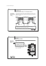
Page 37: ...ERBUS Eingang Lage und Bezeichnung der Anschl sse Digitaler Eingang Stromversorgung bei Fernbusversion ST9 Funktionserde FE BIS C 6021 ffnen der Auswerteeinheit Anschlusspl ne Um den Modus f r die Kom...

Page 38: ...Wenn dieser Fernbusteilnehmer als letzter am Bus angeschlossen ist muss der INTERBUS Ausgang X2 mit einer Verschlusskappe verschraubt werden um die Schutzart zu gew hrlei sten Bitte beachten Sie die B...

Page 39: ...ecker geh use verbinden Adern verdrillt2 9 polige Buchse Ausgang 9 poliger Stecker Eingang Schirm leitend mit Stecker geh use ver binden 1 2 2 2 2 Busteilnehmer BIS C 6021 ST8 Busteilnehmer Busteilneh...

Page 40: ...ssen paarweise verdrillt sein Empfohlener Kabeltyp LiYCY 3x2x0 25 mm2 maximale Kabelkapazit t 120 pF m Schirm leitend mit Stecker geh use verbinden Adern verdrillt2 9 polige Buchse Ausgang 9 poliger S...

Page 41: ...ebs bedingungen Anschlussart Schutzart Elektrische Anschl sse C60_1 023_819395_0508_d p65 82 82 D Digitaler Eingang X1 IN IN ber Optokoppler galvanisch getrennt Steuerspannung aktiv 4 V bis 40 V Steue...

Page 42: ...SYN 44 2C 65 41 A 86 56 V 107 6B k 1 01 Ctrl A SOH 23 17 Ctrl W ETB 45 2D 66 42 B 87 57 W 108 6C l 2 02 Ctrl B STX 24 18 Ctrl X CAN 46 2E 67 43 C 88 58 X 109 6D m 3 03 Ctrl C ETX 25 19 Ctrl Y EM 47 2...

Page 43: ...eutsch bitte wenden C60_1 023_819395_0508_en p65 2 No 819 395 D E Edition 0508 Subject to modification Replaces edition 0506 Balluff GmbH Schurwaldstrasse 9 73765 Neuhausen a d F Germany Phone 49 0 71...

Page 44: ...se an identification system and may only be used for this purpose in an industrial environment in conformity with Class A of the EMC Law Installation and operation should be carried out by technically...

Page 45: ...controlling material flow in production processes e g in model specific processes for workpiece conveying in transfer lines in data gathering for quality assurance for gathering safety related data i...

Page 46: ...be cable connected to the processor Series BIS C 60_1 processors have in addition a digital input The input has various functions depending on the configuration see Parametering Whether the compact ve...

Page 47: ...508_en p65 10 10 E INTERBUS Communication between the BIS C 60_1 processor and the host system is via INTERBUS The INTERBUS system consists of three components the wiring module rack card for industri...

Page 48: ...e user BUS interface INTERBUS Physical Addressing Logical Addressing C60_1 023_819395_0508_en p65 12 12 E 1 2 3 Compatibility with BIS C 6_1 processor Setting compatibility Compatibility with the BIS...

Page 49: ...ed all the important data it indicates this to the processor by resetting the bit that was set at the beginning AV bit 6 The processor now in turn sets all the control bits that were set during the se...

Page 50: ...output buffer for one 1 read write head Function Description Output Buffer Configuration and Explanation Sub Bit Meaning Function Description address Name 00Hex CT Data carrier type Select data carrie...

Page 51: ...basic procedure on 13 and 28 35 and the examples on pages 36 55 C60_1 023_819395_0508_en p65 18 18 E Description of Output buffer continued Sub Meaning Function Description address 02Hex Start addres...

Page 52: ...rier continued next Description of Output buffer continued Function Description Output Buffer Configuration and Explanation Please note the basic procedure on 13 and 28 35 and the examples on pages 36...

Page 53: ...Sub Bit Meaning Function Description address Name 00Hex continued Bit Header IN Input If the parameter Input IN is 1 this bit indicates the state of the Input AF Command Error The command was incorrec...

Page 54: ...and the examples on pages 36 55 C60_1 023_819395_0508_en p65 24 24 E Sub Meaning Function Description address 02Hex Configuration 2nd byte 80Hex Default value factory setting Does not change or Data D...

Page 55: ...gital input of the processor IN 0 digital input low IN 1 digital input high Reset BIS C 60_1 processor through the digital input If this function is activated the processor is reset when the digital i...

Page 56: ...ost sends to the output buffer the command designator to subaddress 01Hex the start address for reading or writing to subaddress 02Hex 03Hex the number of bytes for reading or writing to subaddress 04...

Page 57: ...is no data carrier in the active zone of the read write head If dynamic mode is configured the processor accepts the read write job and stores it When a data carrier is recognized the stored job is ca...

Page 58: ...is used like a normal write job The latter is rejected with an error message if the processor recognizes that the data carrier does not contain the correct CRC Data carriers as shipped from the factor...

Page 59: ...uding the command identifier and program number The individual program records must all be contiguous They must be sent one after the other and be terminated with FFHEXFFHEX as a terminator It is reco...

Page 60: ...sed BIS C 1_ _ 03 L with 32 byte block size Because 2 bytes are used for the CRC only 120 bytes can be used as data bytes hence start address 0 number of bytes 120 5 Process subaddresses of the output...

Page 61: ...the input buffer in order shown 3 Process subaddresses of the input buffer 4 Process subaddresses of the input buffer 6 Process subaddresses of the input buffer 5 Process subaddresses of the input buf...

Page 62: ...s Process subaddress of the output buffer 00Hex 07Hex Invert TI Bit Example No 3 like 2nd example but with simultaneous data transmission For configuring with double bit header Continued on next BIS C...

Page 63: ...taneous data transmission For configuring with double bit header Read 30 bytes starting at data carrier address 10 with read error and simultaneous data transmission data carrier type with 64 byte blo...

Page 64: ...and AF Bit 5 Process subaddress of the input buffer Function Description Examples for protocol sequence C60_1 023_819395_0508_en p65 44 44 E Example No 7 For configuring with double bit header Write 1...

Page 65: ...it 01 06Hex Copy first 6 data bytes Process subaddress of the output buffer 00Hex 07Hex Invert TI Bit Example No 8 Continued on next BIS C 60_1 Identification System 2 Process subaddresses of the inpu...

Page 66: ...le bit header Storing a program for reading out 3 data records 1st data record Start address 5 Number of bytes 7 2nd data record Start address 75 Number of bytes 3 3rd data record Start address 312 Nu...

Page 67: ...addresses and number of bytes with FFHex Continued on next Function Description Examples for protocol sequence C60_1 023_819395_0508_en p65 50 50 E 00Hex 07Hex Reset AV Bit 00Hex 07Hex Reset AA Bit an...

Page 68: ...mples for protocol sequence 00Hex 07Hex Set AA Bit 01 06Hex Enter first 6 bytes of data 00Hex 07Hex Set AE Bit C60_1 023_819395_0508_en p65 52 52 E Example No 12 Mixed Data Access For configuring with...

Page 69: ...on data can be programmed in both buffers for Head 1 and Head 2 as desired Host 1 Process subaddresses of the output buffer in the order shown BIS C 60_1 Identification System 2 Process subaddresses o...

Page 70: ...ta carrier is not yet recognized an additional 45 ms for building the required energy field until the data carrier is recog nized must be added For double read and compare Data carrier with 32 byte bl...

Page 71: ...5 from 0 to 31 112 from 0 to 63 224 C60_1 023_819395_0508_en p65 58 58 E Function displays on BIS C 60_1 The BIS C 60_1 uses the three side mounted LED s to indicate important conditions of the ident...

Page 72: ...te INTERBUS 19 18 17 16 15 14 13 12 11 10 9 8 7 6 5 4 3 2 1 X5 Head 1 Head 2 UL CC BA RD Function displays C60_1 023_819395_0508_en p65 60 60 E Mounting the read write head or adapter BIS C 6001 Mount...

Page 73: ...ghtening torque 0 15 Nm C60_1 023_819395_0508_en p65 62 62 E BIS C 6001 Installing the connection cables The BIS C 6001 processor must be opened in order to make the connections for the supply voltage...

Page 74: ...BIS C 6001 processors into the serial INTERBUS the terminal strip provides terminals 1 5 for the input interface and terminals 8 12 for the output interface of the INTERBUS The following drawing show...

Page 75: ...e twisted pair Recommended cable LiYCY 3x2x0 25 mm2 AWG 24 maximum cable capacitance 120 pF m Shield connected to connector housing twisted pair2 Input terminal block 9 pin MIN D female output 9 polig...

Page 76: ...ure that the shield makes a good connection with the PG housing Please note the installation instructions on 63 C60_1 023_819395_0508_en p65 68 68 E Connection for read write head 8 pin BIS C 6001 Int...

Page 77: ...mm Dimensions with adapter BIS C 650 approx 184 x 90 x 35 mm Weight approx 400 g Ambient Temperature 0 C to 60 C Terminal Block 19 pin Cable Entry for supply voltage 1 x PG 9 fitting metal for INTERB...

Page 78: ...336 EEC EMC Guideline and the EMC Law Testing in our EMC Laboratory which is accredited by the DATech for Testing of Electromagnetic Compatibility has confirmed that Balluff products meet the EMC requ...

Page 79: ...tions and names Digital input power supply for ST9 remote bus version Function ground FE BIS C 6021 Opening the processor Wiring Diagrams To convert the processor for the power supply via the installa...

Page 80: ...e on the bus the INTERBUS output X2 must be closed off with a threaded cap to maintain the enclosure rating Please note the load capacity of the INTERBUS cable and verify during operation that the sup...

Page 81: ...r housing twisted pair2 9 pin female output 9 pin male input Connect shield to connector housing 1 2 2 2 2 Bus station BIS C 6021 ST8 Bus station Bus station 9 pin female X2 output 9 pin male X3 input...

Page 82: ...nd DI must be twisted pair Recommended cable LiYCY 3x2x0 25 mm2 AWG 24 maximum cable capacitance 120 pF m Connect shield to connector housing twisted pair2 9 pin female output 9 pin male input Connect...

Page 83: ...nsions weight Operating conditions Connection type Enclosure Electrical connections C60_1 023_819395_0508_en p65 82 82 E Digital input X1 IN IN galvanically isolated optocoupler Control voltage active...

Page 84: ...65 41 A 86 56 V 107 6B k 1 01 Ctrl A SOH 23 17 Ctrl W ETB 45 2D 66 42 B 87 57 W 108 6C l 2 02 Ctrl B STX 24 18 Ctrl X CAN 46 2E 67 43 C 88 58 X 109 6D m 3 03 Ctrl C ETX 25 19 Ctrl Y EM 47 2F 68 44 D 8...

Reviews: