Consolidated 2900-40 Series POSRV Instruction Manual
| 39
© 2020 Baker Hughes Company. All rights reserved.
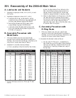
A. Lubricants and Sealants
1. Operating temperatures below -40°F (-40°C), consult
the Factory.
2. Operating temperatures above -40°F (-40°C)
a. Lubricate all O-Rings, except silicone, spring
energized seals, and back-up rings sparingly with
silicone grease (Baker Hughes P/N SP505).
b. Seal all pipe threads with Teflon tape or pipe
sealant (Baker Hughes P/N SP364-AB).
c. Lubricate standard threads and bearing points
with nickel graphite N5000 (Baker Hughes P/N
4114507) or equivalent.
B. Assembly Procedure with
Metal Seats
1. If the valve Nozzle was removed, apply thread
lubricant to the nozzle threads before reinstalling in
the Base. Insert it into the inlet flange of the Base, and
torque to the correct value listed in Table 9.
2. Assemble the disc/disc holder as follows:
a. Prior to assembly of the Disc into the Disc Holder,
remove the Disc Retainer from the back of the
Disc. Use 1000 grit grinding compound on the
bearing surface to grind the Disc into the Disc
Holder to properly establish the bearing surface.
b. Place the Disc Retainer into the groove in the disc.
The Disc with the Disc Retainer should “snap”
into the Disc Holder pocket with moderate finger
or hand force. Do not use excessive force to
assemble these parts. Be sure that the Disc is free
to “wobble” after it is in place.
C. Assembly Procedure with
O-Ring Seats
1. If the valve Nozzle was removed, apply thread
lubricant to the nozzle threads before reinstalling in
the Base. Insert it into the inlet flange of the Base, and
torque to the correct value listed in Table 9.
2. Assemble the disc/disc holder as follows:
a. For disc sizes “D” through “J”, reassemble the
Disc Holder using a new O-Ring, O-Ring Retainer,
and new Lock Screw(s). Refer to Table 10 for the
proper torque. These Disc Holders are ready for
the next step.
XVI. Reassembly of the 2900-40 Main Valve
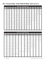
Table 9: Nozzle Torque 0 / -10%
Orifice
Required Torque
1
ft-lbs
Nm
D
165
223.71
E
165
223.71
F
165
223.71
G
145
196.59
H
165
223.71
J
335
454.20
K
430
583.00
L
550
745.70
M
550
745.70
N
640
867.72
P
1020
1382.93
Q
1400
1898.15
R
1070
1450.73
T
1920
2603.17
Table 10: Disc Holder Torque Values
Orifice
No. of
Bolts
Bolt Size
Torque
in-lbs
N-m
D
1
1/4-28UNF
75
± 3
8.5
± 0.3
E
1
1/4-28UNF
75
± 3
8.5
± 0.3
F
1
1/4-28UNF
75
± 3
8.5
± 0.3
G
1
1/4-28UNF
75
± 3
8.5
± 0.3
H
1
1/4-28UNF
75
± 3
8.5
± 0.3
J
3
#10-32UNF
30
± 2
3.4
± 0.2
K
3
#8-32NC
18
± 1
2.0
± 0.1
L
3
#8-32NC
18
± 1
2.0
± 0.1
M
4
#8-32NC
18
± 1
2.0
± 0.1
N
4
#8-32NC
18
± 1
2.0
± 0.1
P
4
1/4-28UNF
75
± 3
8.5
± 0.3
Q
4
1/4-28UNF
75
± 3
8.5
± 0.3
R
4
1/4-28UNF
75
± 3
8.5
± 0.3
T
4
1/4-28UNF
75
± 3
8.5
± 0.3
1.
DO NOT USE impact wrench on "D" through "K" orifice
Nozzles.

