Consolidated 2900-40 Series POSRV Instruction Manual
| 59
© 2020 Baker Hughes Company. All rights reserved.
XXII. 2900-40 Series POSRV Options
When the pilot operated safety relief valve is not vented
directly to atmosphere, it is possible to build up
backpressure in the discharge line. This is typical in
situations where several valves manifold into a common
discharge header. Should the discharge line pressure
exceed the valve inlet pressure, it could cause the disc to
lift and allow reverse flow through the main valve. This
situation can be eliminated through the use of the Backflow
Preventer.
A.1 Disassembly Instructions
1. Remove Shuttle Plug from Shuttle Base by unscrewing
counterclockwise.
2. Remove Shuttle Ball, Tube Filter, and O-Rings and
discard.
A.2 Cleaning
1. If required, clean parts to remove all rust, burrs, scale,
organic matter, and loose particles. Parts are to be free
of any oil or grease except for lubrication as specified in
this instruction.
2. Cleaning agents used shall be such that effective
cleaning is assured without injuring the surface finishes
or material properties of the part.
3. Acceptable cleaning agents include demineralized
water, nonphosphate detergent, acetone, and isopropyl
alcohol. Parts must be blown dry or wiped dry after
cleaning.
4. If you are using cleaning solvents, take precautions to
protect yourself from potential danger from breathing
fumes, chemical burns, or explosion. See the
solvent’s Material Safety Data Sheet for safe handling
recommendations and equipment.
5. It is not recommended to “sand blast” internal parts as it
can reduce the dimensions of the parts.
A.3 Parts Inspection
1. Shuttle Base: Galling or excessive wear on the threads.
Check for any corrosion or pitting.
2. Shuttle Plug: Galling or excessive wear on the threads.
Check for any corrosion or pitting.
A.4 Reassembly Instructions
Lubricate O-Rings with silicone grease Baker Hughes P/N
SP505.
1. Assembly of Field Test Connection / Backflow
Preventer Assembly.
a. Insert one of the Small O-Rings into the Shuttle
Base counter bore.
b. Insert the Tube Filter into the Shuttle Base.
c. Insert Shuttle Ball inside of Tube Filter.
d. Insert the other Small O-Ring into the Shuttle Plug
counter bore. Install Larger O-Ring into groove
located on OD of Shuttle Plug.
e. Thread Shuttle Plug into Shuttle Base, wrench
tighten.
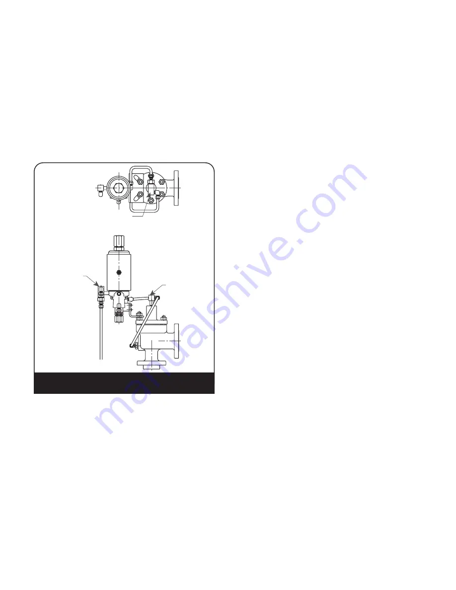
Backflow
Preventer
Backflow
Preventer
Field Test
Connection
Figure 45: Field Test Connection /
Backflow Preventer Option
A. Backflow Preventer

