38 |
Baker Hughes
© 2020 Baker Hughes Company. All rights reserved.
9. O-Ring Seated Disc: The O-Ring Retainer cannot
be machined. It can be lapped for minor scratches.
If lapping does not fix damaged area, part must be
discarded.
10. Disc Holder: Disc Holder should be replaced if the
sliding surface of the Holder is galled, pitted, or
scratched.
11. Solid Metal Gaskets: Solid Metal Gaskets can be
reused unless they are corroded, pitted, or crimped.
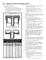
12. Main Valve Piston Replacement Criteria:
The Piston should be re-used if:
a. There is no indication of galling, scratched,
corroded or pitted on any surface of the piston.
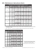
b. The “B” & “E” dimensions (See Figure 27) are less
than “B” minimum and “E” minimum, indicated in
Table 8.
Replace all parts as needed. If any damage listed above
is present, the part should be replaced or repaired per
instruction. Other valve parts may be acceptable with light
corrosion, pitting, or minor damage of other types if it can
be determined that it will not affect product performance.
All O-Rings and seals should be replaced each time the
valve is disassembled.
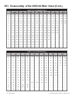
Refer to Tables 20
for a list of recommended spare parts
and Table 21 for a list of O-Ring repair kits.
XV. Inspection and Part Replacement (Cont.)
Table 7: Thermodisc Replacement Criteria
Orifice
A min.
Orifice
A min.
in.
mm
in.
mm
D
.006
0.15
L
.014
0.36
E
.006
0.15
M
.014
0.36
F
.006
0.15
N
.014
0.36
G
.006
0.15
P
.017
0.43
H
.006
0.15
Q
.015
0.38
J
.013
0.33
R
.015
0.38
K
.014
0.36
T
.025
0.64
C
B
D
A
E
Figure 27: Main Valve Piston
C
D
B
E
A
Figure 27a:
D-H Orifice
Figure 27b:
J-T Orifice
Table 8: Piston Critical Dimensions
Orifice
B min.
E min.
in.
mm
in.
mm
D
.989
25.12
.748
19.00
E
.989
25.12
.748
19.00
F
.989
25.12
.748
19.00
G
1.114
28.30
.873
22.17
H
1.365
34.67
.998
25.35
J
1.677
42.60
1.310
33.27
K
1.990
50.55
1.623
41.22
L
2.490
63.25
2.123
53.92
M
2.867
72.82
2.498
63.45
N
3.117
79.17
2.748
69.80
P
3.741
95.02
3.372
85.65
Q
4.861
123.47
4.498
114.25
R
5.735
145.67
5.372
136.45
T
7.360
186.94
6.997
177.72
A
C
B
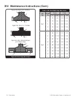
Figure 26: Thermodisc
Figure 26a: Type 1 (D-H Orifices)
Figure 26b: Type 2 (J-T Orifices)
A
B
C

