24 |
Baker Hughes
© 2020 Baker Hughes Company. All rights reserved.
XII. Recommended Installation Practices (Cont.)
Example: the condensed steam in the pilot and tubing
may become frozen.
3. Applications where the process media is temperature
sensitive to thick formations.
Example: hydrocarbon applications where the
possibility of hydrate formation may occur.
Reasons for Freeze Protection:
1. If the pilot sensing line becomes clogged or frozen,
then system pressure can be isolated from the pilot
valve. This will not allow the pilot to detect system
pressure, open and relieve the overpressure situation.
Recommendations for insulating and heat tracing pilot
operated safety relief valve:
Types of freeze protection:
a. Insulation by fiberglass blankets or wrap.
b. Heat tracing with electrical heat tape.
c. Radiant heat sources, such as a heat lamp.
For applications where heat tracing or radiant heaters are
used, the temperature should be limited to approximately
200ºF (93.3ºC) so that the elastomers are not damaged.
Higher temperatures may be allowed upon review of the
application.
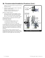
Valve illustrations showing acceptable locations for
insulation are shown in Figures 8 and 9. Figure 8 shows a
standard pilot operated relief valve. Figure 9 shows a pilot
operated relief valve equipped with a heat exchanger.
Insulation
not required
for Bonnet
and Cap
Do not insulate
or cover
Heat Exchanger
top or bottom
Outside perimeter
of Heat Exchanger
may be insulated.
Cover Plate
Pilot
Valve
Main Valve
Base
Figure 9: POSRV with Heat Exchanger


