34 |
Baker Hughes
© 2020 Baker Hughes Company. All rights reserved.
F. Precautions and Hints for
Lapping Seats
To ensure a quality lapping process, observe the following
precautions and guidelines:
Keep work materials clean. Always use a fresh lap. If signs
of wear (out of flatness) are evident, recondition the lap.
Apply a very thin layer of lapping compound to the lap to
prevent rounding off the edges of the seat.
Keep the lap squarely on the flat surface, and avoid
rocking the lap, which causes rounding of the seat.
When lapping, keep a firm grip on the lapped part to
prevent dropping it and damaging the seat.
Lap in a circular motion while applying a uniform pressure.
Slowly rotate the lap to evenly distribute the lapping
compound. Wipe off the old compound and replace it
with new compound frequently. Apply more pressure to
speed the cutting action of the compound. To check the
seating surfaces, remove all compound from the seat
and the lap. Then, shine the seat with the same lap using
the lapping method as described above. Low sections
on the seating surface show up as shadow in contrast to
the shiny portion. If shadows are present, further lapping
is necessary. Only laps known to be flat can be used. It
should take only a few minutes to remove the shadows.
When lapping is complete, any lines appearing as cross-
scratches can be removed by rotating the lap on its axis
(which has been wiped clean of compound) on the seat.
Thoroughly clean the lapped seat using lint free cloth and
a cleansing fluid.
ATTENTION!
!
Before assembly, grind the contact surfaces of the nozzle
and O-Ring retainer to provide metal-to-metal seat
tightness in the event of O-Ring failure.
G. Reconditioning of Laps
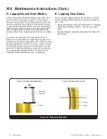
Ring laps are reconditioned by lapping them on a flat
lapping plate in a figure-eight motion (Figure 20). To
ensure the best results, recondition the ring laps after each
use. Use an optical flat to check the quality of the lap.
Nozzle laps must be re-machined to recondition the
lapping surfaces. Place the nozzle lap in a lathe between
centers (Figure 21). The surfaces marked A and B must be
running concentric.
H. Re-Machining Nozzle Seats
1. Remove the nozzle from the valve to be remachined.
If it cannot be removed from the base, re-machine it
inside the base.
2. Take the following steps to setup the lathe and nozzle:
a. Grip the nozzle in a four-jaw independent chuck (or
collet, if appropriate), using a piece of soft material
such as copper or fiber between the jaws and the
nozzle as shown at A (Figure 22).
b. True up the nozzle so that the surfaces marked B
and C run true within .001” (0.03 mm) on indicator
(Figure 22).
LAPPING PLATE
RING LAP
Figure 20: Lapping Pattern
Lathe Center
Lathe Center
A
C
D
B
85°
90°
Figure 21: Nozzle Lap in a Lathe
XIV. Maintenance Instructions (Cont.)


