


B9 Scan 500 Operating Manual
Page40
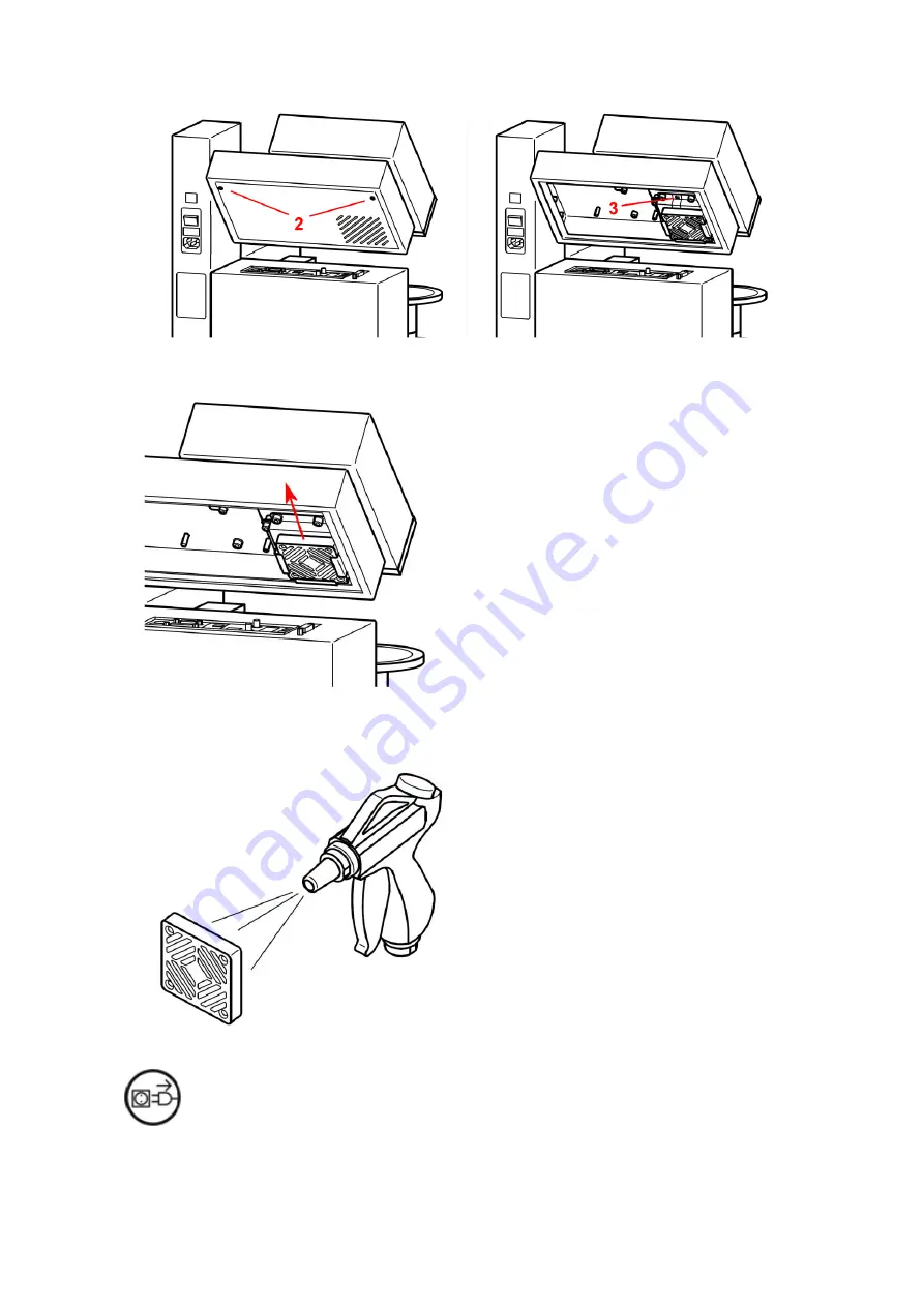
4.
Remove the filter by hands moving it in the arrow direction.
5.
Use a blow of low pressure compressed air to clean it. Direct the air blow as shown in the
figure. If necessary, replace the entire filter.
DISCONNECT FROM MAINS
•
Always disconnect the equipment from electrical power before removing a fuse; not doing
so may result in serious injury.
Summary of Contents for B9 Scan 500
Page 1: ...B9 Scan 500 Operating Manual...
Page 31: ...B9 Scan 500 Operating Manual Page31...
Page 45: ...B9 Scan 500 Operating Manual Page45 Specifications B9 Scan 500 Package weight 24 Kg...
Page 47: ...B9 Scan 500 Operating Manual Page47 Model Company Product Label B9 Scan 500 14 3 DIMENSIONS...
Page 48: ...B9 Scan 500 Operating Manual Page48 14 4 ELECTRICAL CIRCUIT DIAGRAM...
Page 49: ...B9 Scan 500 Operating Manual Page49 15 OPERATIONS CHECK LIST Putting into operations...
Page 54: ...B9 Scan 500 Operating Manual Page54 KEYWORD INDEX No index entries found...


