


5-18
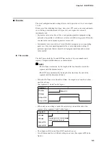
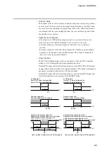
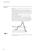
• G.SOAK at end of segment
PV and SP are compared at the end of the segment. The operation in that
segment ends when the absolute value continues beyond the G.SOAK time and
becomes narrower than G.SOAK width.
A G.SOAK wait state continues until these conditions are met which is
announced by the flashing of the linear LED at the center of the profile display.
The operating condition is the same as HOLD at the end of a segment (time =
set segment time).
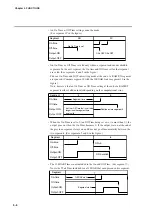
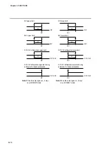
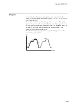
• G.SOAK for entire segment
PV and SP are compared at across the entire segment. The operation in that
segment continues when the absolute value continues beyond the G.SOAK time
and becomes narrower than G.SOAK width.
A G.SOAK wait state continues until these conditions are met which is
announced by the flashing of the linear LED at the left and the center of the
profile display.
The operating condition is the same as HOLD at the continued time.
■
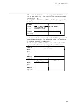
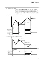
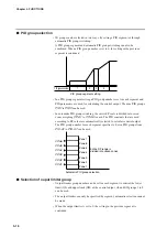
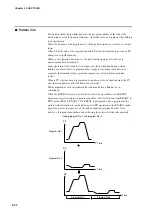
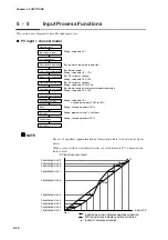
PV shift
A PV correction value can be set for each segment. PV is PV input value plus PV
bias and PV shift. Note, however, that in the READY mode and the constant value
control mode, PV bias but not PV shift is added to the PV input value.
The setting in the previous segment continues when PV shift is set to “-----”
(nothing).
G. SOAK
width
G. SOAK
width
SP
PV
Segment
setting time
G.SOAK wait time
Time
SP
Chapter 5. FUNCTIONS
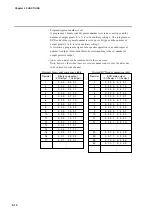
Segment number
1
2
3
4
5
6
Nothing Nothing
+5˚C
N10˚C
0˚C
PV shift setting
+5˚C
+10˚C
Time
SP
PV
PV input value
+5˚C setting is continued.
A “No PV shift setting” that continues from the first
segment has the same effect as a PV shift 0°C setting.


