


12-1
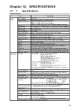
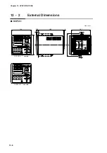
Chapter 12. SPECIFICATIONS
12 - 1
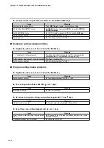
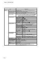
Specifications
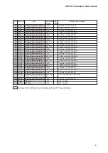
Item
Specifications
Program
section
Input section
No. of programs
99 programs
No. of segments
99 segments/1 program, or total 2000 segments
Segment time
0 to 500 hours 00 min, 0 to 500 min 00sec, or 0.0 to 3000.0sec (Time unit is switchable.)
Segment slope
1 to 10000U/hours, 1 to 10000U/min, or 1 to 10000U/sec (Time unit is switchable.)
No. of sub-function
4000 settings
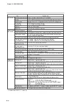
Event (16 point)
Operating point set as specified by event type.
PID group setting
Group 0 (continuing from previous segment), groups 1 to 9, group A (automatic
changeover) and ON-OFF control settable.
Output limiter group
Group 0 (continuing from previous segment), groups 1 to 9 settable
G.SOAK
Type (start point, end point, all) and G.SOAK width 0 to 1000U settable
PV shift
-10000 to +10000 settable
Repeat
Return segment number and repeat count settable.
PV start
Type settable for each program (ascending, descending and bi-directional)
Cycle
Cycle count number settable for each program
Pattern link
Program numbers 0 to 99 (program 0 without link) settable for each program
Tag
8 characters consisting of alphanumerics, katakana and symbols settable for each program
Basic time accuracy
-0.01% (segment time setting = 0, repeat; each cycle and repeat slows the process by 0.1sec)
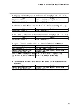
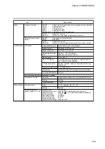
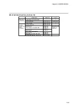
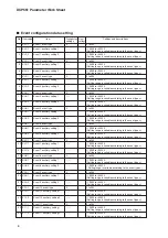
Input type
Input sampling cycle
0.1s
Input bias current
Thermocouple, DC voltage input: Max.
±
1.3
µ
A (peak value, under standard
conditions). The range higher than 1V is Max. -3
µ
A.
Measurement current
RTD input: approx. 1mA, Current input on terminal A. (under operating conditions)
Influence of wiring
resistance
Thermocouple, DC voltage input: Thermocouple
: 0.5
µ
V/
Ω
DC voltage (lower than 1V range) : 0.5
µ
V/
Ω
DC voltage (5V range)
: 3
µ
V/
Ω
DC voltage (10V range)
: 6
µ
V/
Ω
Resistance temperature detector input: Max.
±
0.01% FS/
Ω
within wire resistor 0 to 10W
The ranges of F01, F33, P01, and P33 are Max.
±
0.02% FS/
Ω
.
Allowable wiring resistance
(Resistance temperature
detector input)
• The ranges except F01, F33, P01, and P33 are lower than 85
Ω
.
• The ranges of F01, F33, P01, and P33 are lower than 10
Ω
.
Allowable parallel resistance
Thermocouple disconnection detection allowable parallel resistance: Higher than 1M
Ω
.
Max. allowable input
Thermocouple, DC voltage input:-5 to +15Vdc
DC current input : 50mAdc, 2.5Vdc
Burn out
Burnout on/off selectable
Range over assessment
100% FS or more: upscaled
-10% FS or less : downscaled
(However, inputs in the F50 range are not downscaled.)
Sub-function function
Event, PID group, output limiter group, G.SOAK, PV shift, repeat
Cold junction compensation accuracy
±
0.5˚C (under standard conditions)
Segment
∆
SP
1 to 10000U/1 pulse
Segment setting system
RAMP-X: Setting by set points (SP) and time.
RAMP-T: Setting by set points (SP) and slope (
θ
).
RAMP-E: Setting by set points (SP) or
∆
SP per pulse of external switch input.
Input impedance
DC current input: approx. 50
Ω
(under operating conditions)
Thermocouple:
K, E, J, T, B, R, S (JIS C1602-1981)
WRe5-26 (Hoskins Data)
PR40-20 (Johnson Matthey Data)
N (N.B.S. Monograph 161)
PLII (Engelhard Industries Data (IPTS68))
Ni-NiMo (General Electric Data)
Gold iron chromel (Hayashidenko Data)
Resistance temperature detector (RTD):
Pt100,JPt100 (JIS C1604-1989)
DC current:
4 to 20mA, 2.4 to 20mA
DC voltage:
0 to 10mV, -10 to +10mV, 0 to 100mV, 0 to 1V, -1 to +1V,
1 to 5V, 0 to 5V, 0 to 10V
Multi-range of thermocouple, resistance temperature detector, DC voltage, and
DC current(see page 2-8, 2-9).


