


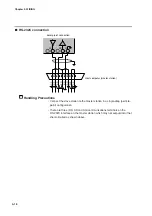


5-8
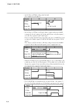
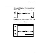
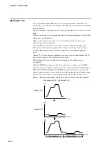
• When there is a G.SOAK at the end of the previous segment, the On Time in
the next segment is ignored if it is set to 0. (See segments 11 and 12 in the
figure.)
Thus the ON = 0 of segment 12 is not output at the end of the set time for
segment 11, but when the G.SOAK wait ends.
• This function can be combined with an event ON delay set using PARA. Delay
works when an event goes from off to on. A delay is not triggered when an On
Time continues across two segments as shown in segments 5 and 6 in the
figure.
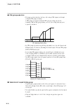
●
PV event
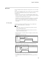
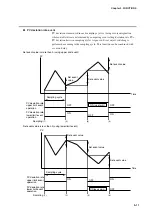
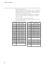
• Basic specifications
The difference between PV, deviation, absolute value deviation, SP, MV and
PV1-PV2 for each event type is shown on the following pages. The thick lines
show ON and OFF conditions. The upper line indicates ON and the lower line
indicates OFF conditions.
EV indicates the event set value and H indicates the hysteresis value. Outputs in
READY mode are OFF. But normal PV1 upper and lower limit operation and
normal PV2 upper and lower limit operation events run also in the READY
mode.
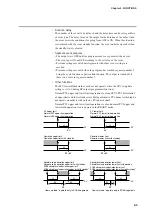
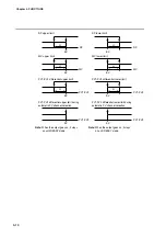
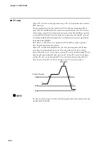
• Event standby
Standby events operate as described below.
• If the event is in the gray area
shown in the figure during a change from
READY to RUN mode or when the power is restored after an outage, the
event operates without a standby. The upturned arrows in the figures indicate
ON while the downturned arrows indicate OFF.
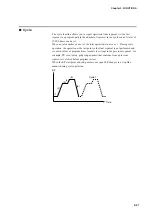
• If the event is outside the gray area
shown in the figure during a change
from READY to RUN mode or when the power is restored after an outage, it
remains off until it enters the gray area
.
After entering the gray area
, the upturned arrows in the figures indicate
ON while the downturned arrows indicate OFF.
A standby event is off in the READY mode.
12
ON=0
11
Segment time
G.SOAK wait
Segment
Segment
On-time
Off-time
Output-ON
Output-OFF
On-time
Off-time
Output-ON
Output-OFF
Chapter 5. FUNCTIONS


