AXIOMATIC Tri-Axial J1939 CAN User Manual Download Page 10


UMAX0608XX‐1000. Tri‐Axial J1939 CAN Inclinometer. Version 9B 

Page: 10-66

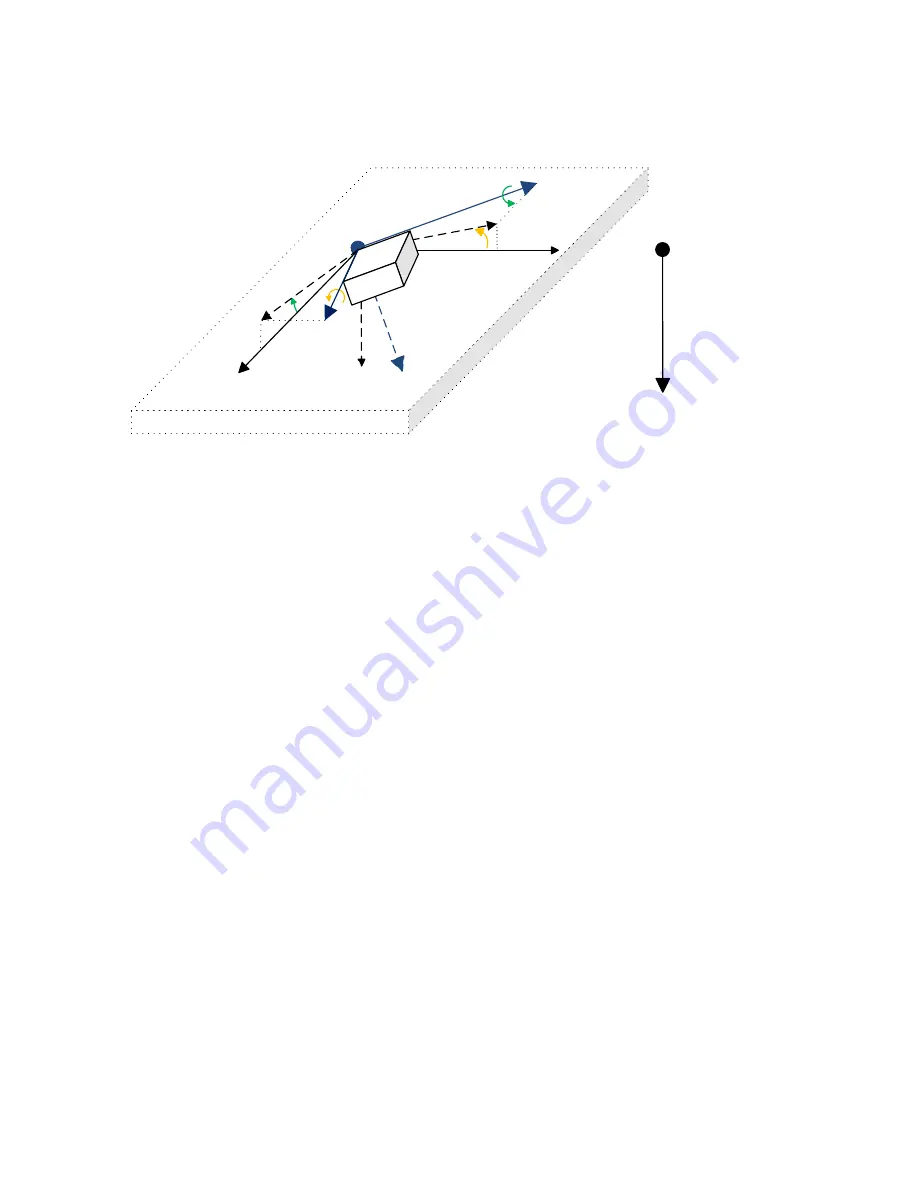
2.1.3.2.1 Unit Rotation Angles 

The unit rotation angles define rotations about the axes in the unit frame (X,Y,Z) the following 
way, see Figure 4. 

X‐ Axis

Y ‐ Axis

Z‐ axis

Plane (X

E

,Y

E

) is parallel to the Earth surface

θ

u

 ‐ Pitch

φ

u

 ‐ Roll

X

E(XZ)

*

Y

E(YZ)

*

θ

u

 > 0

φ

u

 < 0

Gravity vector 


𝑔


is coincident 

with the Z

E

 axis


Y

E

X

E

Z

E


Figure 4. Simple Rotation Angles 

 
The rotation about the Y-axis defines the pitch angle 

𝜃

 and the rotation about the X axis – the 

roll angle 

𝜙

. The pitch angle 

𝜃

 is an angle between the horizontal projection X

E(XZ)

*

 of the 

unit X axis onto the (X

E

,Z

E

) plane and the X

E

 axis. Similarly, the roll angle 

𝜙

 is an angle 

between the horizontal projection Y

E(YZ)

*

 of the unit Y axis onto the (Y

E

,Z

E

) plane and the Y

E


axis.  
 
The (X

E

,Z

E

) and (Y

E

,Z

E

) planes are perpendicular to the Earth surface (X

E

,Y

E

) in the Earth 

frame (X

E

,Y

E

,Z

E

). The angle between X

E(XZ)

*

 and Y

E(YZ)

*

 is always 90°. 

 
The rotation about the Z-axis (yaw angle) is not shown in Figure 4. It cannot be calculated 
based on the gravity acceleration 

𝑔⃗

 
The sign of the pitch and roll angles is defined by the right-hand rule and presented by the 
arrows about the Y and X axes. Since the pitch angle 

𝜃

 direction in Figure 4 is the same as 

the positive direction defined by the yellow arrow about the Y axis, the angle is positive. The 
same way, the roll angle 

𝜙

 direction is the opposite to the positive direction defined by the 

green arrow about the X axis. Therefore, the roll angle 

𝜙

 in Figure 4 is negative. 

 
The unit rotation angles are calculated using the following formulas: 

𝜃

𝑎𝑡𝑎𝑛2 𝑔 , 𝑔

𝜃 ∈

180

°

; 180

°

,

(7) 

𝜙

𝑎𝑡𝑎𝑛2 𝑔 , 𝑔

,  

𝜙 ∈

180

°

; 180

°

,


where: 𝑔

𝑎 , 𝑔

𝑎 ,  𝑔

𝑎 .


The roll-over condition is observed when: 

|𝜃 |

90

°

 or 

|𝜙 |

90

°

 
When the unit is parallel to the Earth surface, the unit rotation angles are zero: 

𝜃

𝜙


Summary of Contents for Tri-Axial J1939 CAN

Page 1: ...38 Vertical Mount Two M12 Connectors Both CAN P N AX060806 AX060810 One DT15 4P Connector P N AX060807 AX060811 One DT15 4P Connector CAN Termination In Europe Axiomatic Technologies Oy H yt m ntie 6...

Page 2: ...rth GPS Global Positioning System Grms Root Mean Square Acceleration in G units Hz Hertz IEC International Electrotechnical Commission LSB Less Significant Byte MEMS Microelectromechanical system NED...

Page 3: ...nating Resistors 19 2 5 Default Settings 19 2 5 1 CAN Interface 19 2 5 1 1 PGN 61459 Slope Sensor Information SSI 19 2 5 1 2 PGN 61481 Slope Sensor Information 2 SSI2 21 2 5 1 3 PGN 65256 Vehicle Dire...

Page 4: ...Configuring Analog Signal Outputs 49 5 FLASHING NEW FIRMWARE 51 6 TECHNICAL SPECIFICATIONS 55 6 1 Performance Parameters 55 6 1 1 Angular Measurements 55 6 2 Power Supply Input 55 6 3 CAN Output 56 6...

Page 5: ...anual front page The user manual is usually valid for application firmware with the same major version number as the user manual For example this user manual is valid for any inclinometer application...

Page 6: ...through a set of configuration parameters to fit the user specific application requirements using Axiomatic Electronic Assistant software 2 1 Theory of Operation 2 1 1 Unit Coordinate System The incli...

Page 7: ...e position of the machine when it is leveled on the operation area The unit calculates accelerations and angles referred to the machine frame XM YM ZM Conversion from the unit frame X Y Z to the machi...

Page 8: ...le defines the inclination of the unit relatively the gravity vector The pitch and roll tilt angles define the inclination of the unit relatively to the XE YE ground plane parallel to the Earth surfac...

Page 9: ...0 where 1 0 1 0 and When measured in the 90 range the tilt angles are the angles that a dual axis inclinometer or two single axis inclinometers placed in orthogonal directions will measure in the same...

Page 10: ...YE axis The XE ZE and YE ZE planes are perpendicular to the Earth surface XE YE in the Earth frame XE YE ZE The angle between XE XZ and YE YZ is always 90 The rotation about the Z axis yaw angle is n...

Page 11: ...An intermediate coordinate system XE YE ZE is a Z down coordinate system whose XE and YE axes are parallel to the ground plane XE YE with the XE axis aligned with the vertical projection of the X axis...

Page 12: ...allel to the gravity vector see Figure 6 When this happens the unit effectively loses one degree of freedom and the roll angles and become undefined and can take any random value Z axis Y Axis X Axis...

Page 13: ...high for the angular measurements 2 1 3 4 Practical Recommendations In the beginning the user defines an inclinometer position on the machine direction of the measurement angle or two angles in ortho...

Page 14: ...ints 180 range for pitch and roll angles Roll over detection Numerically unstable pitch and roll angles in gimbal lock points Euler Angles Smooth angular transition inside the measurement range except...

Page 15: ...hole measurement range Dual Axis Angle 90 Tilt Angle 90 Angular position in space Smooth angular transition No No No Tilt Angle 180 Pitch angle 180 Euler Angle Unit Rotation Angle No Yes Yes Yes Yes F...

Page 16: ...necessary information see Figure 9 EMI Filter Transient and Reverse Polarity Protection BAT BAT Power Supply 3D Accelerometer ARM Cortex M3 Microcontroller CAN CAN_HI CAN_LO CAN_SHIELD CAN_SHIELD is a...

Page 17: ...ess messages PGN 65240 ECU identification messages ECUID PGN 64965 and software identification messages SOFT PGN 65242 It also supports responses on PGN Requests PGN 59904 Please note that the Proprie...

Page 18: ...are presented in the table below Table 3 J1939 Name Fields Field Name Field Length Field Value Configurable Arbitrary Address Capable 1 bit 1 Capable No Industry Group 3 bit 3 Construction Equipment...

Page 19: ...r is shipped with the following pre configured settings to transmit angular data on the CAN bus 2 5 1 CAN Interface By default the inclinometer angular data is transmitted in a standard PGN PGN 61481...

Page 20: ...eter Name Pitch Rate Not used by the inclinometer Populated with 0xFFFF Data Length 2 bytes Resolution 0 002 deg sec per bit 64 offset Data Range 64 to 64 51 deg sec Operational Range same as data ran...

Page 21: ...ing parameters Transmission Repetition Rate 10 ms Data Length 8 Default Priority 3 Parameter Group Number 61481 Start Position Length Parameter Name SPN 1 3 3 bytes Pitch Angle Extended Range 4976 4 6...

Page 22: ...ded Range Compensation Not used by the inclinometer Populated with 11b Data Length 2 bits Bit 2 Bit 1 0 0 On 0 1 Off 1 0 Error 1 1 Not available Type Status Parameter Name Roll Angle Extended Range Fi...

Page 23: ...h Operational Range same as data range Type Measured Parameter Name Pitch Data Length 2 bytes Resolution 1 128 deg bit 200 deg offset Data Range 200 to 301 99 deg Operational Range 200 deg DECENT to...

Page 24: ...igured as 0 5 V voltage outputs the following way1 AOUT1 Pitch Angle 90 0 V 90 5 V AOUT2 Roll Angle 90 0 V 90 5 V AOUT3 Gravity Angle 0 0 V 180 5 V 1 In firmware versions 4 xx 7 xx Voltage Range is se...

Page 25: ...are defined by theconfiguration parameters Analog Signal Output 1 3 AOUT1 AOUT2 AOUT3 Present only in AX061000 Figure 10 The Inclinometer Logical Block Diagram Each function block is absolutely indepe...

Page 26: ...ppropriate configuration parameter There is no limitation on the number of signal inputs connected to a signal output When a signal input is connected to a signal output data from the signal output of...

Page 27: ...nal value configuration parameter is used in a function block In this case the configuration parameter value is used as a signal value when the signal is not defined see Binary Function blocks 3 2 Acc...

Page 28: ...gle Angular Measurement Latency Angular Figure of Merit Gravity Acceleration Error Figure 12 Angle Measurement Function Block The Pitch Angle continuous signal output defines the unit pitch angle in d...

Page 29: ...it Rotation Angle is not supported in firmware V1 xx 3 Not supported in firmware V1 xx The Tilt Angle Range is assumed to be 180 in firmware V1 xx 3 4 Unit Installation The Unit Installation function...

Page 30: ...en the machine is in the initial null angle position leveled on the operation area The machine frame is coincident with the Earth reference frame in this position see Unit Reference Frames The user sh...

Page 31: ...otation In the same way a horizontal mounting unit AX060800 can be converted into a vertical mounting unit AX060808 now legacy p n with a different original unit frame orientation using 90 90 0 coordi...

Page 32: ...ed technician They are also written in a setpoint file together with other configuration parameters 3 6 Binary Functions There are ten Binary Function blocks available to the user for performing simpl...

Page 33: ...y F x y y if x y min x y Minimum F x y x if x y F x y y if x y Equal F x y 1 if x y F x y 0 if x y Not Equal F x y 1 if x y F x y 0 if x y Great F x y 1 if x y F x y 0 if x y Great Equal F x y 1 if x...

Page 34: ...a1 Scale 1 Offset 1 0 Any value b1 Offset 1 Input 2 Signal Source Not Connected Any signal output of any function block or Not Connected X2 Input Signal 2 Input 2 Signal Default No No Yes Defines whet...

Page 35: ...nted as zero voltage in Output Voltage mode In Output Current mode the undefined signals are presented as zero current in 0 20mA and 0 24mA ranges or as 4mA in the 4 20mA range If the signal value is...

Page 36: ...lock also contains Supply Voltage continuous signal output presenting the inclinometer supply voltage in V Please note that this voltage is not the voltage on the inclinometer power supply connector p...

Page 37: ...multiple inclinometers on the same CAN network The list of available ECU instances is shown in the ECU Instance Number Setup dialog window in EA The user should select the required ECU instance numbe...

Page 38: ...Fast slew rate in this case is used when the distance between CAN nodes substantially exceeds 40 m the maximum value defined by the J1939 11 15 standard 3 10 CAN Input Signal There are three CAN Inpu...

Page 39: ...If Autoreset Time is 0 the auto reset is disabled 1Proprietary A PGN 61184 is excluded It is taken by Axiomatic Simple Proprietary Protocol and therefore cannot be used in function blocks The CAN inpu...

Page 40: ...e Function Block Configuration parameters of the CAN Output Message function block are presented below Table 17 CAN Output Message Function Block Configuration Parameters Name Default Value1 Range Uni...

Page 41: ...s Offset of the 2 nd CAN continuous output signal Signal 10 Type Undefined Undefined Discrete Continuous Type of the 10 th CAN output signal Signal 10 Source Not Connected Any signal output of any fun...

Page 42: ...s are presented in the signal code with all bits set to 1 Discrete signals are directly assigned to the signal code without any conversion Continuous signals are converted to the signal code based on...

Page 43: ...the user should use EA 5 15 108 0 or higher with the inclinometer application firmware version 9 xx described in this user manual The most recent EA software version can be downloaded from Axiomatic w...

Page 44: ...r function block is presented by its own setpoint group in the Setpoint File main group Individual configuration parameters setpoints of a function block can be accessed through the function block set...

Page 45: ...UMAX0608XX 1000 Tri Axial J1939 CAN Inclinometer Version 9B Page 45 66 Figure 26 Accelerometer Function Block in EA Figure 27 Changing a Configuration Parameter in EA...

Page 46: ...the setpoint file view or print it and also flash the setpoint file into the inclinometer see Figure 28 Figure 28 EA Setpoint File The CAN network identification and read only configuration parameter...

Page 47: ...5280 PDU2 Proprietary Start Position Length Parameter Name SPN 1 1 2 bits User Alarm Flag N A Parameter Name User Alarm Flag Data Length 2 bits Bit 2 Bit 1 0 0 Off Platform is not tilted 0 1 On Platfo...

Page 48: ...n Rate 100 ms Length 1 Byte Priority 6 J1939 CAN Bus Signal 1 Type Discrete Signal 1 Byte Position 1 Signal 1 Bit Position 1 Signal 1 Size 2 Bit Figure 29 Block Diagram of the Example Configuration Fi...

Page 49: ...clinometer configuration is finished Now the unit operates according to the new user requirements The configuration parameters are all set and are already written to the non volatile unit memory The u...

Page 50: ...ction provides the tilt alarm internal signal see Figure 29 Then set Output Mode to Output Voltage Voltage Range to 0 5 V Scale to 5 and Offset to 0 see Figure 32 Figure 32 Analog Signal Output 3 Exam...

Page 51: ...originally shipped with older versions of the application firmware the user should request a special application firmware file compatible with the installed bootloader version to upgrade the inclinome...

Page 52: ...nformation controller hardware bootloader details and the currently installed application firmware remains the same in the bootloader mode and the user can read it in the Bootloader Information group...

Page 53: ...the user can add any comments to the flashing operation in the Flashing Comments field They will be stored in the Bootloader Information group after flashing The user can also check the Erase All ECU...

Page 54: ...running the new firmware see Figure 38 This will indicate that the flashing operation has been performed successfully For more information refer to the J1939 Bootloader section of the EA user manual F...

Page 55: ...061000 Resolution 0 06 Effective Resolution 3 46 NoiseRMS Maximum at cut off frequency Fc 5Hz accelerometer range 1 5g Initial Accuracy 2 Maximum Temperature Drift 3 Maximum in the full temperature ra...

Page 56: ...t s 120Ohm Internal Terminating Resistor AX060800 AX060806 AX060808 AX060830 AX061000 AX060838 AX060810 No AX060807 AX060811 Yes Bosch CAN protocol specification 2 0 Part A B For the internal CAN cont...

Page 57: ...set to 10 10V Pitch Angle 90 10V 90 10V Roll Angle 90 10V 90 10V Gravity Angle 0 10V 180 10V 6 5 General Specifications Table 23 General Specifications Parameter Value Remarks Sensor Type MEMS Intern...

Page 58: ...Resistor Sensor AX060800 AX060800 Two M12 Connectors No Regular AX0608081 AX060806 AX060806 4 pin Deutsch DT15 4P connector AX060807 Yes AX060830 AX060800 Two M12 Connectors No High performance AX0610...

Page 59: ...out Inclinometers in AX060800 enclosure have two versions of the pinout 6 7 1 1 1 CAN Only The CAN only pinout is used in inclinometers AX060800 AX060808 AX060830 AX060838 that do not have any other i...

Page 60: ...42 This orientation is suitable for a horizontal installation X Y Z Z points away from the viewer Roll Pitch Figure 42 Horizontal Unit Frame Orientation The legacy vertical mount inclinometers AX06080...

Page 61: ...different part number on the label but retain the same pinout and unit orientation 6 7 2 1 Connector Pinout Inclinometers AX060806 AX060807 AX060810 AX060811 have the following connector pinout see F...

Page 62: ...V5 00 6 8 Installation See mechanical installation information on the dimensional drawings The CAN wiring is considered intrinsically safe All field wiring should be suitable for the operating temper...

Page 63: ...ek Bogush Updated Analog Signal Output Default Settings for AX061000 in Technical Specifications Updated Analog Outputs in Default Settings Updated Analog Signal Output Function Block Configuration Pa...

Page 64: ...Orientation sub sections Added Analog Signal Output Default Settings for AX061000 in Analog Outputs sub section Updated CAN Parameters CAN and Analog Signal Outputs 4C 4 xx 5 13 98 0 or higher Nov 16...

Page 65: ...version numbering in Version History 3B 3 xx 5 13 90 0 or higher August 4 2017 Olek Bogush In Static Parameters sub section changed Resolution remarks for clarity Added P N AX070140 for M12 sealing ca...

Page 66: ...iptions 1D 1 xx 4 11 81 0 or higher March 29 2017 Olek Bogush Added DP15 4P versions Updated Hardware Block Diagram Network Bus Terminating Resistors and Technical Specifications sections 1C 1 xx 4 11...

Page 67: ...m Please provide the following information when requesting an RMA number Serial number part number Axiomatic invoice number and date Hours of operation description of problem Wiring set up diagram app...

Reviews: