


CRANE
CO.
280
N.
MIDLAND
AVE.,
STE
258,
SADDLE
BROOK,
NJ
07663
WWW.AVIDCONTROLS.COM
12/17/12
TECH-440/D.W.O. 23135
Page 48 of 55
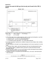
Control Schematic for Wiring of Intrinsically safe SmartCal for ATEX & IECEX
(Sheet 2 of 2)
Entity parameters for each field wiring terminal pair of SmartCal:
Vmax = 30V
Imax = 100mA Pi=0.75 Watt
Ci = 0 pF
Li = 17.25 uH
ATEX Notes:
1. Barrier must be a ATEX certified, single channel grounded shunt-diode zener barrier or single
channel isolating barrier or one dual channel or two single channel barriers may be used where both
channels have been certified for use together with combined entity parameters.
The following conditions must be satisfied:
Voc or Vo
Vmax or Ui
Ca > Ci + Ccable
Isc or Io
Imax or Ii
La
>
Li
+
Lcable
2. Associated apparatus manufacturer’s installation drawing must be followed when installing this
equipment.
3. Control equipment connected to associated apparatus must not use or generate more than 250V.
4. To maintain intrinsic safety, each field wiring pair (4-20 mA and Analog Output) must be run in
separate cables or separate shields connected to intrinsically safe (Associated Apparatus) ground.
5. Where rigid metal conduit is not used, seal SmartCal cable entries against dust and fibers using an
appropriate NRTL listed cable gland fitting.
6. Installation should be in accordance with EN 60079 and / or the local / national electrical codes of
practice.


