326
Maintenance Procedures
December 2003
4
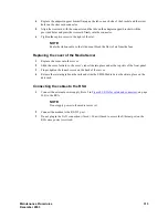
Release the retaining tabs on the rails and slide the S8500 Media Server back into place on the
data rack.
5
Locate the marked cable that you removed from the old NIC and plug it into the Ethernet 2 port,
which is labeled ACT/LINK A on the small faceplate of the new NIC.
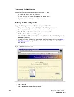
Powering up the server
Complete the following steps if you wish to start the media server at this time:
1
Plug the power cord into the power receptacle on back of the server.
2
Press the Power button located on the front right-hand side.
3
Login to the server after the startup to ensure that the installation is complete.
Checking LED activity on the dual NIC
When the Media Server is back in service, check the LEDs on each port of the dual NIC (
S8500 rear panel dual NIC LEDs,
Figure 100: S8500 rear panel dual NIC LEDs
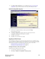
Confirming original Ethernet configuration
After the Media Server is back in service, check the original Ethernet configuration settings:
1
Go to the Configure Server Web page.
2
Confirm that the server’s Ethernet configuration settings are the same as before.
Figure notes
1
Network activity LED (Tx/Rx)
2
Connection rate:
•
LED is off: there is a 10 BASE-T active link.
•
LED is green: there is a 100 BASE-T active link.
•
LED is orange: there is a 1000 BASE-T active
link.
1
2
LINK TX/RX
LINK TX/RX
PCI
1
PCI 2
100-127 -, 3,0A, 50/60 Hz
200-240 -, 1,5A, 50/60 Hz
133 MHz/64 Bit, 100 MHz/64 Bit
h3msble2 KLC 082503
100-127 -, 3,0A,
200-240 -, 1,5A, 5
1
2
Summary of Contents for CMC1
Page 1: ...Maintenance Procedures 555 245 103 Issue 1 1 December 2003 ...
Page 14: ...Contents 14 Maintenance Procedures December 2003 ...
Page 416: ...Additional maintenance procedures IP Telephones 416 Maintenance Procedures December 2003 ...
Page 426: ...Index X 426 Maintenance Procedures December 2003 ...


