18
Easy Slider - Sliding Gate Opener
Owner Installation Instructions
Setting travel limits
�� �� � � � �
� � �
�� � � � � � � � �
�� � � �
17
fig
19
fig
20
fig
�� � �� � � �
� � �
� � � � � � � � � � �
�� �
�� � � �
�� �� � � � � � � �
�� � �
�� � � �� � �
�� � � �
18
fig
�� � � �� � �
��� � �
� � � � � � �� �
�� � � �
�� � � � � � �
� � �� � �
�� � � �
� � � � �
� ��
�� � � �
�� � � �
�
21
fig
Dual leaf gate
This section shows how to set the travel limits for
a dual leaf gate installation. The procedure can be
partly completed using a transmitter. In order to use a
transmitter it must first have at least one of its buttons
coded to the gate controller. The function assigned
to the transmitter’s buttons during coding is of no
concern here as the buttons are temporally assigned
to OPEN, CLOSE and SET.
NOTE:
The limit setting
procedure can be aborted at anytime by pressing EXIT.
NOTE:
Gate should be moved manually to half open
position. When re-engaging opener nudge gate until
click is heard to confirm pinion gear has engaged fully.
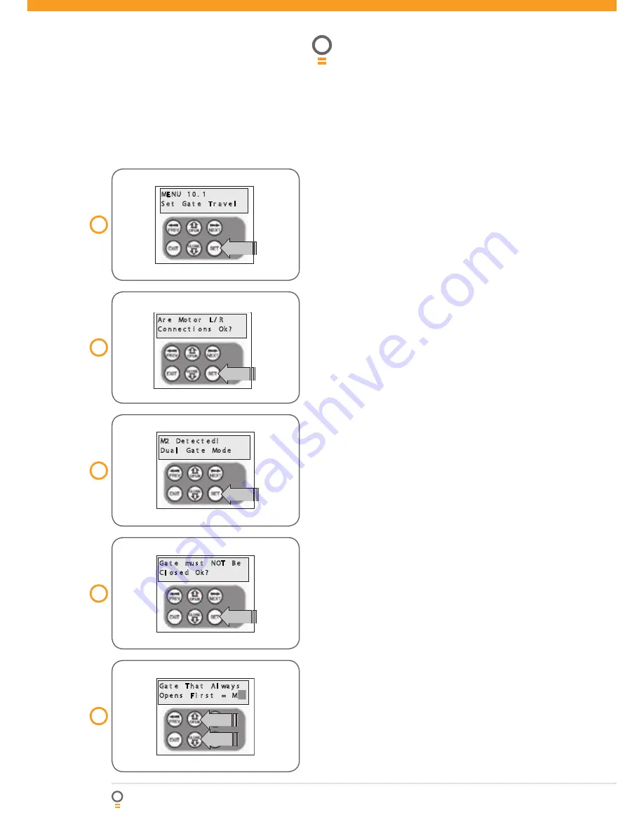
Step 1. Navigating to “set gate travel menu”
1. Press PREV to navigate to the Menu 10
(Fig. 17)
.
2. Press SET to display MENU 10.1.
3. Press SET again to enter the limit setting procedure.
Step 2. Setting the left/right connector
1. Confirm motor connection is set for correct
sides
(Fig. 18)
.
2. Press SET to confirm.
Step 3. Confirming dual gate mode
The controller will now determine whether a single or
dual gate installation is required by trying to detect the
presence of a second drive unit. As this is a dual gate
installation, the screen below should be shown. Press
SET to continue. If Single Gate Mode is displayed then
check the connections between the two drive units and
press EXIT to restart from step 2
(Fig. 19)
.
Step 4. Confirming gates are not closed
Before proceeding, the gates must not be in the closed
position. This is so that each leaf can be moved freely
without interfering with the other. If the gates are
closed, partially open them manually, then re-engage
them. Press SET to continue
(Fig. 20)
.
Step 5. Selecting which motor opens first
during normal operation
The controller prompts to select which motor will open
first during normal operation. The selected motor is
also used for pedestrian access.
1. Use OPEN or CLOSE to change display
to M1 or M2
(Fig. 21)
.
2. Press SET to save the selection.
NOTE:
M1 is selected for the purpose of this
instruction manual.
NOTE:
The motor selected will determine the order
in which each motor will be processed in the following
steps. The procedure documented here shows the
steps for when M1 is selected. If M2 is selected to
open first, then the displayed motor numbers will be
the opposite to those shown here.


