Depending on the DCS, either a DTM (Device Type Manager) or an EDD (Electronic
Device Description) is required to integrate device-specific information, data and
parameters, which can be accessed via Profibus DP-V1, into the engineering station.
The availability of the Profibus DP-V1 services is preset in the factory. For a
description of the DP-V1 services, refer to the appendix.
4.4.
Redundancy
— Option —
To increase the security of the installation, the actuator controls may be equipped
with a redundant Profibus DP interface.
The following redundant operation modes are supported:
1.
Redundant behaviour according to AUMA redundancy (AUMA redundancy I or
AUMA redundancy II)
(use of AUMA 0C4F.GSD in combination with the ident. no. of the standard
version: 0x0C4F)
2.
Redundant behaviour according to Profibus DP-V2 redundancy in accordance
with PNO guideline 2.212 (system redundancy or flying redundancy)
(use of AUMA AUMA 0CBD.GSD in combination with the ident. no. of the
standard version: 0x0CBD)
The redundant behaviour is set using the following parameter:
Device configuration
>
Profibus
>
Redundancy M0601
4.4.1.
Redundant behaviour according to AUMA redundancy
This redundancy type can be selected if the DCS does not support Profibus DP-V2
redundancy according to Profibus DP guideline 2.212 but a redundant structure is
nevertheless required.
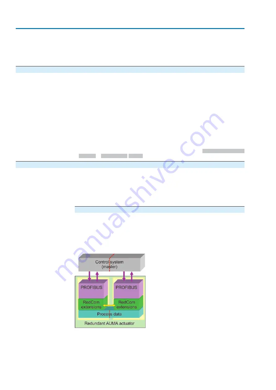
The physical structure of the redundant Profibus DP interfaces within the controls is
based on two independent, galvanically isolated Profibus DP interfaces with an
internal RedCom data channel for exchanging the communication status.
AUMA redundancy I
In general, the actuator decides autonomously which of the Profibus DP
communication channels will be the active channel and therefore be able to operate
the actuator and which channel will be the passive channel only providing feedback
signals of the actuator. The slave addresses can be individually assigned for
both channels.
Figure 1: Basic structure for AUMA redundancy I
The operation of both communication channels is logically, physically and
chronologically separated.
The communication channel, which first exchanges process data with the controls
(data exchange state), is the active channel, the second channel will automatically
become the passive channel. The actuator can only be controlled via the active
channel.
42
Actuator controls
Description of the data interface
AC(V) 01.2/AC(V)ExC 01.2 Profibus DP
Summary of Contents for AC(V) 01.2
Page 1: ...Actuator controls AC V 01 2 AC V ExC 01 2 Profibus DP Device integration Manual...
Page 22: ...22 Actuator controls Description of the data interface AC V 01 2 AC V ExC 01 2 Profibus DP...
Page 89: ...89 Actuator controls AC V 01 2 AC V ExC 01 2 Profibus DP...
Page 90: ...90 Actuator controls AC V 01 2 AC V ExC 01 2 Profibus DP...


