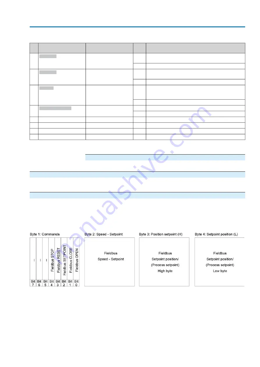
Table 26: Byte 32: SIL indications
Description
Value
Prm-Text-Def GSD file
Designation
(process representation)
Bit
Safe ESD (Emergency Shut Down) safety function of the
SIL sub-assembly is active.
1
(204) = "Safe ESD"
Safe ESD
1)
1
No signal
0
Safe STOP safety function of the SIL sub-assembly is
active.
1
(205) = "Safe Stop"
Safe Stop
1)
2
No signal
0
Collective signal
Warning: A SIL fault of the SIL sub-assembly has oc-
curred.
1
(206) = "SIL fault"
SIL fault
1)
3
No signal
0
A safety function of the SIL sub-assembly is active.
1
(207) = "SIL function act-
ive"
SIL function active
1)
4
No signal
0
No signal (reserved)
—
—
4
No signal (reserved)
—
—
5
No signal (reserved)
—
—
6
No signal (reserved)
—
—
7
The safety function indications via fieldbus are for information only and must not be used as part of a safety function. The I/O signals of
the SIL module must be used for this purpose.
1)
Byte 33 to byte 40: Reserve
The contents are reserved for future extensions.
4.2.
Output data (process representation output)
The master (controls) can control the slave (actuator) via the process representation
output.
4.2.1.
Process representation output arrangement
Information
To perform remote operations, the selector switch must be in position Remote
control (REMOTE).
35
Actuator controls
AC(V) 01.2/AC(V)ExC 01.2 Profibus DP
Description of the data interface
Summary of Contents for AC(V) 01.2
Page 1: ...Actuator controls AC V 01 2 AC V ExC 01 2 Profibus DP Device integration Manual...
Page 22: ...22 Actuator controls Description of the data interface AC V 01 2 AC V ExC 01 2 Profibus DP...
Page 89: ...89 Actuator controls AC V 01 2 AC V ExC 01 2 Profibus DP...
Page 90: ...90 Actuator controls AC V 01 2 AC V ExC 01 2 Profibus DP...


