background image

8

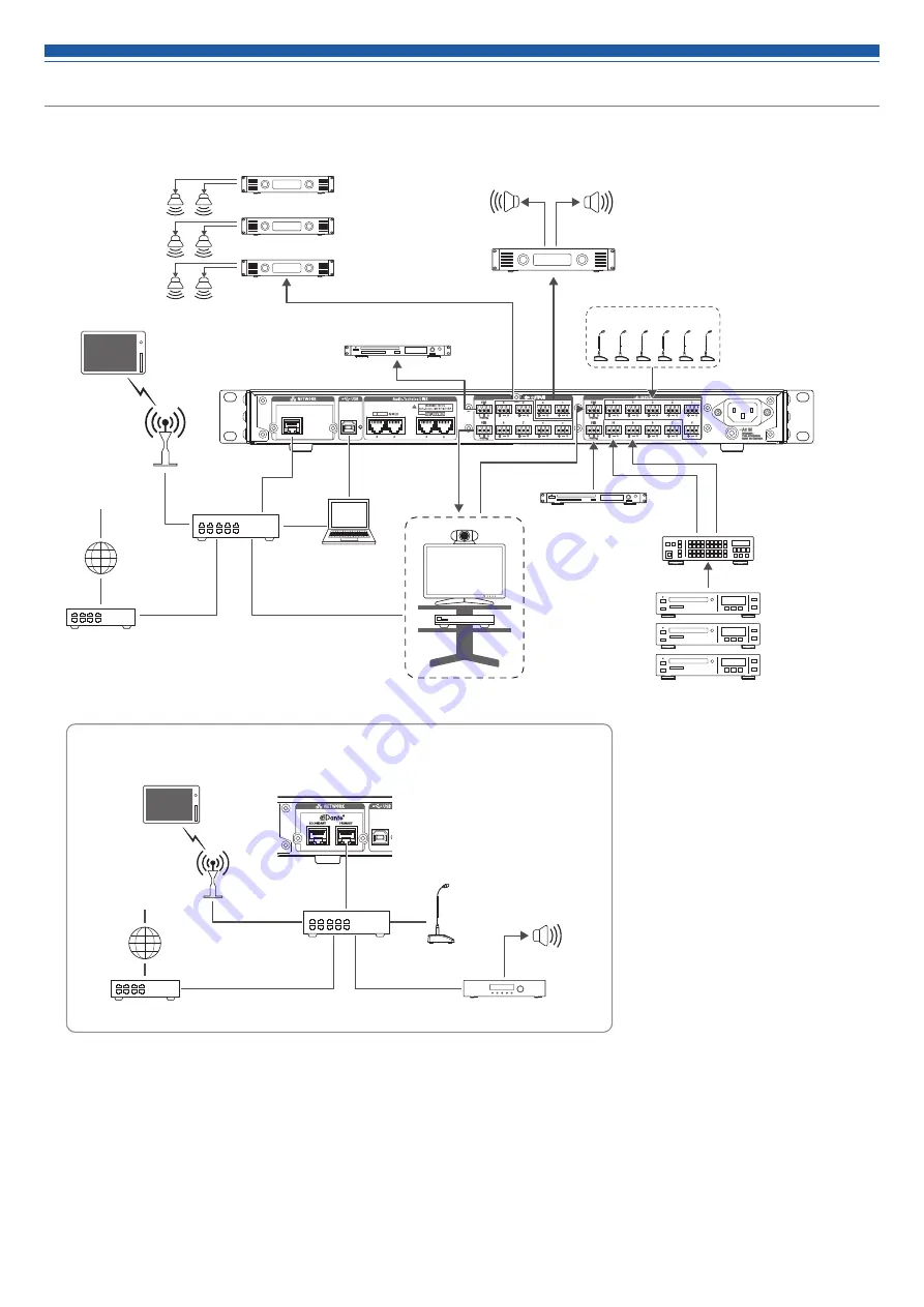
System connection examples

Web 

Remote 

for operator 

Web 

Remote 

for operator

Power amplifier

Media recorder

Media player

Main speaker (L)

Main speaker (R)

Near-end source

Players such as 
Blu-ray/DVD/CD

AV switcher

Video 

conference 

system

Computer

Far-end source

Far-end source

Dante-enabled 

microphone

Router

Internet

Main speaker

Dante-enabled DSP/amplifier

Internet

Switching hub

Router

Far-end source

AP

AP

Power amplifier

Tablet / Smartphone

Tablet / Smartphone

PoE-supported 
switching hub

ATDM-1012DAN

Ceiling speaker

Mic

Summary of Contents for ATDM-1012

Page 1: ...User Manual ATDM 1012 DIGITAL SMARTMIXER ATDM 1012DAN DIGITAL SMARTMIXER with Dante ...

Page 2: ...DM 1012 ATDM 1012DAN unit Euroblock connector 22 Power cable Quick Start Guide Trademarks SMARTMIXERTM is a trademark or registered trademark of Audio Technica Corporation Apple and the Apple logo are trademarks of Apple Inc registered in the U S and other countries iOS is a trademark or registered trademark of Cisco in the U S and other countries App Store is a service mark of Apple Inc Google th...

Page 3: ...risk of shock to persons The exclamation point symbol within an equilateral triangle is intended to alert the user to the presence of important operating and maintenance servicing instructions in the literature accompanying the product Important Safety Instructions 1 Read these instructions 2 Keep these instructions 3 Heed all warnings 4 Follow all instructions 5 Do not use this apparatus near wat...

Page 4: ...s and can radiate radio frequency energy and if not installed and used in accordance with the instructions may cause harmful interference to radio communications However there is no guarantee that interference will not occur in a particular installation If this equipment does cause harmful interference to radio or television reception which can be determined by turning the equipment off and on the...

Page 5: ...may be generated in the TV or radio In this case move the product away from the TV or radio antenna Maintenance If the product becomes dirty or dusty disconnect the power cable first and then wipe the product off with a dry soft cloth Do not use benzine thinner contact restoring protective agent or any other chemical agent Doing so may cause deformation damage or malfunction When storing the produ...

Page 6: ...nt panel whereas the advanced settings can be configured on a computer using Web Remote Allows for external control with IP Remote Protocol A Dante equipped model ATDM 1012DAN is available About Audio Technica LINK Up to eight ATDM 1012 model mixers can be daisy chained so that as a whole system it can handle audio inputs from 80 Mic Line channels and 16 unbalanced stereo channels The proprietary ...

Page 7: ... grounding Electric shock may result if the plug is not grounded securely How to connect a Euroblock connector 1 As shown in the figure expose the wires inside the cable Do not solder the stranded wires 2 Loosen the screws with a flathead screwdriver 3 Verify the pin assignments and connect each to the applicable wire Pin assignments 1 2 3 INPUT 1 to 10 HOT COLD G GND ST1 ST2 R RIGHT L LEFT G GND ...

Page 8: ...d source Players such as Blu ray DVD CD AV switcher Video conference system Computer Far end source Far end source Dante enabled microphone Router Internet Main speaker Dante enabled DSP amplifier Internet Switching hub Router Far end source AP AP Power amplifier Tablet Smartphone Tablet Smartphone PoE supported switching hub ATDM 1012DAN Ceiling speaker Mic ...

Page 9: ...ent setting of the selected channel when the level or gain is being adjusted Dial button Turn the dial button to select and push to confirm the selection An LED can be in one of five statuses 1 Lit Indicates that the channel or preset number is selected that the function is enabled etc 2 Off Indicates that the channel or preset number is not selected that the function is not enabled etc 3 Blinking...

Page 10: ...SB Type B Connect a USB cable with ferrite core Audio Technica LINK A B C D ports Ports for LINK A B C D Used for Audio Technica LINK Connect an Ethernet cable shielded cable of Cat5e or above with the conductor diameter size of 24 AWG or larger must be used Unbalanced output port ST1 ST2 An unbalanced output port Connect an unbalanced cable Pin assignments are as follows R STEREO R L STEREO L G G...

Page 11: ...n to select System Setting and then press the dial button 3 Turn the dial button to select IP Setting and then press the dial button 4 Turn the dial button to select IP Port Set and then press the dial button 5 Turn the dial button to select IP Config Mode and then press the dial button 6 Turn the dial button to select Auto Static and then press the dial button 7 Press the power button to restart ...

Page 12: ...DARY port As shown in the figure a computer or Dante device can be connected directly to the Dante network port of ATDM 1012DAN Redundant Audio In Redundant Audio mode independent networks are necessary for both PRIMARY and SECONDARY If an error occurs on the Dante PRIMARY side network for any reason it will automatically switch to the Dante audio on the SECONDARY network Computer Computer Dante e...

Page 13: ...nels Dante receive channels 1 BUS1 IN1 2 BUS2 IN2 3 BUS3 IN3 4 BUS4 IN4 5 BUS5 IN5 6 BUS6 IN6 7 BUS7 IN7 8 BUS8 IN8 9 BUS9 IN9 10 BUS10 IN10 11 BUS11 IN11 12 BUS12 IN12 13 Direct Output1 IN13 14 Direct Output2 IN14 15 Direct Output3 IN15 16 Direct Output4 IN16 17 Direct Output5 18 Direct Output6 19 Direct Output7 20 Direct Output8 21 Direct Output9 22 Direct Output10 Computer Dante equipped device...

Page 14: ...ers by repeating steps 1 and 2 Use the following procedure to edit characters that have been input To move cursor to the character to be edited 1 Turn the dial button while pressing the BACK button to move the cursor 2 Release the BACK button To delete character that has been input 1 Move the cursor to the character to be deleted 2 While pressing the BACK button press the dial button The character...

Page 15: ...stalling and implementing the product on site Changing the front panel mode operator mode administrator mode 1 While pressing the MODE button press and hold the dial button for 1 or more seconds The front panel mode changes with every press Operator mode Lvl is displayed Administrator mode Aud is displayed Locking the front panel A lock can be applied so that the front panel operation is disabled ...

Page 16: ...ttings switch to administrator mode 1 Turn the dial button on the Home screen to select Set and then press the dial button 2 Turn the dial button to select System Info and then press the dial button 3 Select an item and press the dial button Device Name The name of this product is displayed Device ID The ID number of this product is displayed Serial Number The serial number is displayed FW Version...

Page 17: ...compressor module is assigned 5 Displayed when Smart Mix mode is ON 6 Displayed when set to gate mode when Smart Mix mode is ON 7 Displayed when a Limiter module is assigned Matrix Assign Matrix Assign Set which input channel is sent to which bus or which bus draws from which input channel 1 Turn the dial button on the Home screen to select Aud and then press the dial button 2 Turn the dial button...

Page 18: ... also be selected using the channel selection button 4 Press the dial button The preset data is saved to the specified saving location Setting boot up presets BootUp Presets Sets the recalling presets when the product boots 1 Turn the dial button on the Home screen to select Pst and then press the dial button 2 Turn the dial button to select BootUp Presets and then press the dial button 3 Turn the...

Page 19: ...etwork Time Protocol are displayed NTP Adrs The NTP server address is displayed NTP Port The NTP port number is displayed Time Zone The time difference from UTC Coordinated Universal Time is displayed LINK Status The usage status for Audio Technica LINK Mode is displayed LINK Mode The operation mode for Audio Technica LINK Mode is displayed No ofExtension A The number of connected extensions is di...

Page 20: ... devices must be performed If IP addresses are obtained automatically when connecting 1 Set the product s IP Config Mode to Auto The product ships from the factory in Auto mode 2 Set the control device s network settings so that it connects to the network If static IP addresses are used when connecting 1 Set the product s IP Config Mode to Static The IP address is set to a static value The default...

Page 21: ...ngs Set the options relating to Network Access Permissions Audio Technica LINK etc and update the firmware Operator Access Set the various options relating to the operation screens you can access after logging in as the Operator Presets Recall and save presets and import export preset data to from external devices Logging Set the options relating to log messages and download log messages System In...

Page 22: ... which you want to launch Web Remote Web Remote launches and the Login screen appears Login screen Device name The name set for the product is displayed Mode selection Select Operator or Administrator as the login user Password Enter the password This field appears when login as the Administrator is locked For the password settings refer to Login Password P 48 Login button Language Select the disp...

Page 23: ...e Input channel Red Output channel Icon Display name The icon and display name are displayed as set in Fader Settings P 50 Mute turns ON OFF each time the icon is clicked Recording operation Recording operations can be performed by linking with the TASCAM solid state recorder SS R250N Level meter The level of each channel is displayed Input channel Blue Input received Gray No input Output channel ...

Page 24: ... are operated Device name The name set for the product is displayed Input indicator lamp The input level is displayed Output indicator lamp The output level is displayed Audio Technica LINK status The Audio Technica LINK connection status is displayed IP remote status The active status of IP control is displayed Error status An error status is displayed Preset The selected preset and the name of t...

Page 25: ...is an Audio Technica LINK error IP remote status Remote control is disabled Remote control is enabled There is a remote control error Error status No error is present An error is present Error display When a triangle mark is displayed on an icon clicking the icon displays a description of the error After checking the description of the error move the cursor away from the icon and the triangle mark...

Page 26: ...d out or hidden Click to view the Web Remote version and the Audio Technica website Click to toggle between the audio input matrix and audio output settings screens Click to switch to the Settings Maintenance screen You can configure the audio input settings for each input channel Click each of these items to display a detailed setting menu You can configure the audio output settings for each outp...

Page 27: ...ow to view the Matrix Assign screen Set whether Smart Mix is ON OFF for each channel Set whether AEC is ON OFF for each channel Select the NC bus Switch the ST LINK for the bus ON OFF Set which channel is assigned to which bus ...

Page 28: ...ly when Mic is selected as the input type 1 Click the area in the red box on the screen shown below The setting is turned ON blue OFF no color each time the switch is clicked Turning the phase ON OFF Invert the input audio phase 1 Click the area in the red box on the screen shown below The setting is turned ON blue OFF no color each time the switch is clicked Turning the low cut ON OFF Specify whe...

Page 29: ...ea in the red box on the screen shown below The setting is turned ON blue OFF no color each time the switch is clicked Turning the FBS ON OFF Switch the FBS feedback suppressor between ON and OFF for each channel This setting can be made only when the FBS module is assigned 1 Click CMP FBS 2 Select the check box next to the channel s to which it will be assigned 3 Click the area in the red box on ...

Page 30: ...Setting the audio input details Adjusting the 4 band EQ Set the 4 band EQ to be applied to audio inputs 1 Click the area in the red box on the screen shown below The Settings screen appears 2 Set each item ...

Page 31: ...c state Click this icon in a dynamic state to lock the band and enter a static state Click the icon again to cancel a static state of the band and enter a standby state Standby state Waiting for a new feedback frequency to be detected The frequencies of the detected feedbacks appear Select the strength to suppress the feedback Select the speed of suppressing the feedback Click to reset the detecte...

Page 32: ... pointer Display and switch the ON OFF setting of each band The ON and OFF statuses indicate as follows Turned ON Turned OFF In all bands change the gain to 0 without changing the current frequency Adjust the gain of each band Adjust the frequency of each band Adjust the Q value of each band Change the filter type applicable to bands 1 and 4 only Save an EQ preset reset the EQ frequency response w...

Page 33: ...xpert Mode with all items displayed Easy mode Select from the pre arranged EQ patterns to easily adjust the EQ Expert mode The parameters can be set for each band for finer EQ adjustment Click the icon on the top right of the screen to switch between the two How to view settings screen Easy Mode Select the audio type Adjust the tone ...

Page 34: ...ates the level of audio output from Dynamics Indicates the Dynamics characteristic Set the compressor ratio Set the compressor threshold Set the compressor attack time Set the compressor release time Set the Dynamics output gain When the limiter threshold is lower than the compressor threshold the compressor threshold is cleared and only the limiter threshold is displayed Limiter threshold Compres...

Page 35: ...tch is clicked Checking SmartMixer status 1 Check the area in the red box on the screen shown below Click on the screen to display the SmartMixer Settings screen For more details refer to SmartMixer P 57 Turned OFF Turned ON Turned ON and SmartMixer active Displayed in the set group color Checking bus assignments You can check which channels are assigned to which buses Priority is turned ON if Gat...

Page 36: ...f your choice 4 Click OK Turning the mute ON OFF Switch the mute setting between ON and OFF for each channel 1 Click the area in the red box on the screen shown below Mute turns ON red OFF no color each time the switch is clicked Adjusting the input level Set the Mic Line input level for each channel 1 Drag the volume adjustment dial and move it up and down to adjust the input level Volume adjustm...

Page 37: ...hat primary 1 Click the area in the red box on the screen shown below 2 Select the fader group Setting the Min Max Volume Determine the Min Max Volume and turn it ON OFF for each channel 1 Click the area in the red box on the screen shown below The setting is turned ON blue OFF no color each time the switch is clicked The fader minimum maximum are set at the position when the Min Max Volume is tur...

Page 38: ...t Mix is OFF pressing the button will only switch between ON and OFF 1 Click the area in the red box on the screen shown below Adjusting the volume Adjust the levels for input to each bus 1 Adjust the level by dragging a meter Setting Mono If Mono is turned on the ST CH will be mixed in Mono and can be assigned to each bus Also Mono can be turned on and off separately for each link bus 1 Click the...

Page 39: ...r each channel This setting can be made only when the FBS module is assigned This operation is the same as that for the input channels 1 Click the area in the red box on the screen shown below The setting is turned ON blue OFF no color each time the switch is clicked Turning the EQ ON OFF Switch the EQ between ON and OFF for each channel 1 Click the area in the red box on the screen shown below Th...

Page 40: ...d and enter a static state Click the icon again to cancel a static state of the band and enter a standby state Standby state Waiting for a new feedback frequency to be detected The frequencies of the detected feedbacks appear Select the strength to suppress the feedback Select the speed of suppressing the feedback Click to reset the detected frequencies Once reset new frequencies are detected but ...

Page 41: ...he gain by dragging a pointer Display and switch the ON OFF setting of each band The ON and OFF statuses indicate as follows Turned ON Turned OFF In all bands change the gain to 0 without changing the current frequency Adjust the gain of each band Adjust the frequency of each band Adjust the Q value of each band Change the filter type applicable to bands 1 and 12 only Reset a parameter and save re...

Page 42: ...essor attack time Release Set the compressor release time Select whether to assign the Dynamics as Pre EQ or Post EQ Switch between the compressor and DeEsser Set the Dynamics output gain Set the Limiter threshold Adjust the frequency of the DeEsser Adjust the Q value of the DeEsser Adjust the gain of the DeEsser Change the filter type Turn the Listen function ON OFF Turn the low cut ON OFF When t...

Page 43: ... 1 Click Limiter 2 Select the check box next to the channel s to which it will be assigned 3 Click the area in the red box on the screen shown below The setting is turned ON blue OFF no color each time the switch is clicked Adjusting the dynamics 1 Click the area in the red box on the screen shown below The Settings screen appears 2 Set each item Turning the delay function ON OFF Specify whether o...

Page 44: ...shown below 2 Select a color of your choice 3 Click the text input field and enter the channel name of your choice 4 Click OK Adjusting the output level Set the Mic Line output level for each channel 1 Click the volume adjustment dial and move it up and down to adjust the output level Volume adjustment dial Fader group Min Volume ON OFF Max Volume ON OFF ...

Page 45: ...hat primary 1 Click the area in the red box on the screen shown below 2 Select the fader group Setting the Min Max Volume Determine the Min Max Volume and turn it ON OFF for each channel 1 Click the area in the red box on the screen shown below The setting is turned ON blue OFF no color each time the switch is clicked The fader minimum maximum are set at the position when the Min Max Volume is tur...

Page 46: ...ter another value directly Setting the oscillator The product has an oscillator function on the output channels This function is convenient for checking the audio during setup or maintenance 1 Click Oscillator 2 Click Enable 3 Select between Sine Wave and Pink Noise for the Source 4 Select the frequency next to Frequency 5 Adjust the level next to Level 6 Select the output channels under Assign Wh...

Page 47: ...ting is reflected General in System Settings Device Name Device Name Set the name of the product being controlled from Web Remote Device ID Set the device ID of the product Header Color Set the color of the top part header of the Web Remote screen After setting each item click Apply to complete the setting Audio Technica LINK Mode Set the operation mode under Audio Technica LINK P 60 1 Select Prim...

Page 48: ...ions from IP controlled devices Audio Level Notification Receive audio level notifications from IP controlled devices Multicast Address Set the address for multicast Multicast Port Number Set the port number for multicast This item can be set only when Notification is turned ON blue 2 Click Apply Setting is complete NTP Settings Set the NTP Network Time Protocol 1 Set each item Enabled Set whether...

Page 49: ...nt Panel Restrictions Set whether or not to enable preset recall on the front panel of the product 1 Click the switch to turn on off the setting The setting is turned ON blue OFF no color each time the switch is clicked 2 Click Apply Setting is complete Utilities in System Settings Firmware Update Update the firmware of the product 1 Check Serial No Device Name and Firmware Version on the screen t...

Page 50: ...de from List If the check box is selected fader will be displayed only when accessing from an authorized IP address 3 Set each item Set each item by referring to How to view the Fader Settings screen 4 Click Apply Setting is complete Operator Page Restrictions Set restrictions on the operations that can be performed on the Operator page 1 Set each item Preset Recall Set whether or not to recall pr...

Page 51: ...resets used to save settings for an entire device these presets only save parameters selected by choice Settings can be recalled without affecting parameters other than the saved parameters Changing a partial preset name 1 Click the partial preset name you want to change 2 Enter the new partial preset name Setting partial preset parameters 1 Click the radio button corresponding to the partial pres...

Page 52: ...tting in which the EQ patterns for all bands are saved Library A group that includes all presets Changing a preset name 1 Click the preset name you want to change 2 Enter the new preset name Exporting a preset library 1 Click the radio button corresponding to the preset number from which you want to export Clicking the button selects the preset the color turns to blue When exporting a library you ...

Page 53: ...gs Maintenance System Info in System Info System Info System information such as the various network settings and the product s serial number and firmware version is displayed Clicking Export will export system information to a text file ...

Page 54: ...ing walls or floors of the room and upon being picked up by the microphone is returned to the other party along with your party s audio The other party hears the delayed own audio making it difficult to speak back Using the other party s signals as reference signals the acoustic echo canceler removes only the echoes in the other party s audio from the audio signals sent from your party This makes ...

Page 55: ...urn AEC ON for the microphone to be used for each channel 5 From the Matrix Assign screen NC Bus Select select the signal output bus to be returned to the other party Perform this setting to use the noise canceling function The noise canceling function is set for each bus Access the Matrix Assign screen and set for each bus When setting AEC we recommend setting the noise canceling function on the ...

Page 56: ...luctuates Perform the following procedures as necessary 7 Until the ERL meter is at 0 or less adjust the distance between microphones speaker positions input level etc 8 If necessary turn ON NLP These features may increase the echo canceling effect ...

Page 57: ...n one microphone receives audio input the audio inputs to all open channels are added Simply adding the audio inputs tends to lower the howling margin thereby reducing the audio quality To address this issue the gate mode SmartMixer attenuates the added audio inputs based on the number of open mic channels Gain sharing mode SmartMixer This type of SmartMixer compares the audio input level of each ...

Page 58: ...ate remains open Hold Time Set the time after the audio input is ceased until the microphone input channel gate is closed NOMA This function is used to attenuate the output according to the number of open microphone input channel gates It is recommended that NOMA be set to ON to prevent howling Num of Open Mics Limit the number of microphone input channel gates that open simultaneously Change this...

Page 59: ...e It turns ON purple when clicked 4 Set Weight for each channel as necessary The gain to be distributed can be adjusted This can be used also to balance the background noise for each channel 5 Monitor the gain meter of each channel to confirm that the total gain is distributed based on the input signals ...

Page 60: ...ring pattern Make sure to leave one of the two LINK terminals at both ends of the connected ATDM 1012 devices open For connections use a shielded LAN cable of Cat5e or above with a conductor diameter size of 24 AWG or larger 2 Launch Web Remote and configure the settings related to the Audio Technica LINK for each ATDM 1012 3 In Audio Technica LINK Mode set the ATDM 1012 connected to one of the tw...

Page 61: ...l bus By sharing the AEC reference signal echo canceling of audio shared between the linked primary and extensions is possible Ducking trigger signal bus By sharing the ducking trigger signal ducking can be applied to the stereo input audio of each input audio shared between the linked primary and extensions IN1 BUS1 BUS2 BUS12 AEC Ref Input Processing Matrix Assign Output Source Select Ducking Tr...

Page 62: ... using Audio Technica LINK the audio signals of buses 1 to 4 shared by each mixer can be individually set as triggers by each mixer Preset function When using Audio Technica LINK turning on the Preset Recall LINK for the extension enables the preset of the same number as that of the primary to be applied automatically Operator screen When using Audio Technica LINK the audio levels of each group as...

Page 63: ...annot be activated in Advanced mode 1 Select Administrator and click Login If a password has been set log in by entering that password If you are logged in as an operator log out and then log back in 2 Click the icon on the top right of the screen 3 Click Front Panel 4 In the Levels setting set the operation restriction for the audio level adjustment If INPUT and OUTPUT for each channel are select...

Page 64: ...ice from the pull down menu The preset name appears and the settings change based on the selected preset Administrator screen 1 Click Preset at the top right of the screen 2 Select Recall Preset from the pull down menu 3 Select the preset of your choice The preset name appears and the settings change based on the selected preset ...

Page 65: ...hannel click the currently selected channel to deselect it The selection of the channel is canceled Reselect the channel to copy 4 Select the target channel To select another channel click the currently selected channel to deselect it The selection of the channel is canceled Reselect the target channel 5 Click Paste To cancel the copying click Cancel The screen returns to the previous screen ...

Page 66: ...annels to share the settings Only the following channels can be linked Input channels 7 8 9 10 Sub channels 1 2 3 4 5 6 7 8 Output channels 1 2 3 4 5 6 7 8 1 Click the icon of the channels to be linked 2 Click Link 7 8 3 Confirm that the channels have been linked The settings of channel 8 are same as the settings of channel 7 The linked channel 8 is grayed out and cannot be used ...

Page 67: ... input channels 1 to 4 or 6 to 9 of the ATDM 1012 1 2 3 LED 4 Setting the Administrator Page 1 Start Web Remote and log in as Administrator 2 Click the icon at the upper right of the screen 3 Click Audio ATDM 1012 Ceiling mount AT8554 STP cable MIC1 to MIC3 RJ 45 Breakout cable A MIC1 MIC2 MIC3 MIC4 LED control RJ 45 Breakout cable B STP cable MIC4 LED control ...

Page 68: ...tomatically Virtual Mic 1 2 The input type for input channels 1 to 4 is automatically set as Virtual Mic 1 while the input type for input channels 6 to 9 is automatically set as Virtual Mic 2 Virtual Mic 1 or Virtual Mic 2 can then be selected for the channels The phantom power for input channels 1 to 4 and 6 to 9 turns ON automatically 5 Click Apply 6 Click the screen switch icon 7 Set Input gain...

Page 69: ...c polar pattern Tilt Adjust the directivity of the vertical plane Setting the Operator Page 1 Start Web Remote and log in as Administrator 2 Click the icon at the upper right of the screen 3 Click Operator Page 4 Turn on Array Mic Switch 5 Click Apply Setting is complete 6 Log out and then log in again as an Operator 7 You can turn the ES954 on or off by clicking the Array Mic icon The on or off s...

Page 70: ...sic is playing and there are announcements to be made Enabling Ducking 1 Start Web Remote and log in as Administrator 2 Click Ducking 3 Click Enabled The signal assigned to the selected bus becomes the trigger and ducking is applied to each input channel 4 Using the pull down menu select the trigger bus for the input channel to which ducking is to be applied Ducking for the SUB input channel can o...

Page 71: ... 0dB EQ Off On Off Level 120 0dB to 10 0dB dB dB Mute Off On Off Sub 1 to 8 Source Off Input 1 to 10 Dante1 to 16 Bus 1 to 8 Off Low Cut Off On Off Level 120 0dB to 10 0dB dB dB Mute Off On Off Out 1 to 8 Source Bus 1 to 12 DOUT 1 to 8 Bus 1 to 8 Unity 4dBu 0dBV 10dBV 4dBu FBS Off On Off EQ Off On Off CompInsrt PstFader PreFader PstFader Comp Off On Off Level 120 0dB to 10 0dB dB 40 0dB Mute Off O...

Page 72: ...us 11L Input 1 to 10 S1 S2 Input S2 Bus 12L Input 1 to 10 S1 S2 Input S2 USB OUT Setting USB OUT Out 1 2 Off Bus 1 to 12 Off Level 120 0dB to 0 0dB dB 0 0dB AEC Setting AEC Setting Mode Off AEC NC Off Oscillator Oscillator Output Off On Off Wave Sin 100Hz Sin 1kHz Sin 10kHz Pink Sin 1kHz Level 120dB to 0dB dB dB OSC Out Pst menu Item name Setting values Default Setting Presets Included Resumed Rec...

Page 73: ... Port Set IP Config Mode Auto Static Auto IP Address 0 0 0 0 to 255 255 255 255 empty Subnet Mask 0 0 0 0 to 255 255 255 255 empty Gateway Address 0 0 0 0 to 255 255 255 255 empty Dante Port Set IP Config Mode Auto Static Auto IP Address 0 0 0 0 to 255 255 255 255 XXX XXX XXX XXX Subnet Mask 0 0 0 0 to 255 255 255 255 XXX XXX XXX XXX Gateway Address 0 0 0 0 to 255 255 255 255 XXX XXX XXX XXX Allow...

Page 74: ...ress P XX XX XX XXXX XX Connect Status S N C IP Mode S Auto IP Address S XXX XXX XXX XXX Subnet Mask S XXX XXX XXX XXX Gateway Adrs S XXX XXX XXX XXX Mac Address S XX XX XX XXXX XX Latency 1msec Clock Status N A Allow Discovery On IP Ctrl Port No 17300 IP Ctrl Ntfy Off Audio Level Ntfy Off M cast Adrs 225 000 000 100 M cast Port No 17000 NTP Off NTP Adrs empty NTP Port 00123 Time Zone 00 00 LINK S...

Page 75: ...ff In S1 S2 Level 120 0dB to 10 0dB dB dB Mute Off On Off Sub 1 to 8 Level 120 0dB to 10 0dB dB dB Mute Off On Off Out 1 to 8 Level 120 0dB to 10 0dB dB 40 0dB Mute Off On Off Out S1 S2 Level 120 0dB to 10 0dB dB 40 0dB Mute Off On Off Pst menu Item name Setting values Default Setting Presets Included Resumed Recall Presets Preset 1 to 8 Recall Preset Completed ...

Page 76: ...P Auto IP Address P XXX XXX XXX XXX Subnet Mask P XXX XXX XXX XXX Gateway Adrs P XXX XXX XXX XXX Mac Address P XX XX XX XXXX XX Connect Status S N C IP Mode S Auto IP Address S XXX XXX XXX XXX Subnet Mask S XXX XXX XXX XXX Gateway Adrs S XXX XXX XXX XXX Mac Address S XX XX XX XXXX XX Latency 1msec Clock Status N A Allow Discovery On IP Ctrl Port No 17300 IP Ctrl Ntfy Off Audio Level Ntfy Off M cas...

Page 77: ...g LINE 0dBV LINE 10dBV LINE 20dBV USB LINE 0dBV Input gain 20dB to 20dB 0 4 Band EQ EQ On Off Off CH Name Maximum 10 characters CH ST 1 CH ST 2 CH Color Green Yellow Brown Red Pink Blue Gray Dark Gray Green CH mute Mute On Off Off Levels 120dB to 10dB Max Volume On Off Off Min Volume On Off Off Fader Group A to H OFF OFF Copy Reset Input channels SUB 1 to 8 CH SUB 1 to 8 Mode Select OFF Analog 1 t...

Page 78: ...o 60 0 75 Band 3 Enable On Off On Band 3 Gain 18dB to 18dB 0 Band 3 Frequency 20Hz to 20kHz 6 3k Band 3 Q value 0 3 to 60 0 75 Band 4 Enable On Off On Band 4 Gain 18dB to 18dB 0 Band 4 Frequency 20Hz to 20kHz 16k Band 4 Q value 0 3 to 60 0 75 Band 4 Filter type HPF LSH PEQ PEQ Flat Recall EQ Preset Save EQ Preset Reset Dynamics Setting Comp DeEsser Comp DeEsser Comp Compressor Ratio 1 1 4 1 2 1 4 ...

Page 79: ...umed AEC NC Mode Off AEC NC Off AEC Reference IN6 IN10 IN ST1 IN ST2 OUT1 to 8 OUT ST1 OUT ST2 External OUT1 Send Reference for External On Off Off NC Settings NC Attenuation Level 0dB to 20dB 6 NLP On Off Off NLP Sensitivity Low Mid High Mid Ducking Item name Setting values Default Setting Presets Included Resumed Ducking Target ST1 ST2 SUB 1 2 SUB 3 4 Enabled On Off Off Triggered by Bus 1 to 4 B...

Page 80: ...x Group G1 to G4 G1 Smart Mix Enable Disable Disable AEC Enable Disable Disable Input channels ST1 ST2 CH ST1 ST2 Bus Assign 1 to 12 Off Post SmartMix Bus Pre Bus Assign Level 120dB to 0dB 0 Mono Button On Off Off Input channels SUB 1 to 8 CH SUB 1 to 8 Bus Assign 1 to 12 Off On Pre Off Bus 1 to 12 Bus Stereo LINK Bus 5 6 Bus 7 8 Bus 9 10 Bus 11 12 Off On Off Bus 5 6 Bus 7 8 On Bus 9 10 Bus 11 12 ...

Page 81: ... Link 3 4 Unlink 3 4 Unlink 3 4 Link 5 6 Link 5 6 Unlink 5 6 Unlink 5 6 Link 7 8 Link 7 8 Unlink 7 8 Unlink 7 8 Channel ST1 ST2 CH ST1 ST2 Source Bus 1 2 Bus 3 4 Bus 5 6 Bus 7 8 Bus 9 10 Bus 11 12 Direct Out 9 10 Bus 9 10 Bus 11 12 Unity 0dBV 10dBV 33dBV 0dBV FBS On Off Off EQ On Off Off CMP On Off Off LMT On Off Off Delay Enabled On Off Off CH Name Maximum 30 characters ASCII code only OUT ST 1 O...

Page 82: ...Q value 0 3 to 60 0 75 Band 6 Enable On Off On Band 6 Gain 18dB to 18dB 0 Band 6 Frequency 20Hz to 20kHz 500 Band 6 Q value 0 3 to 60 0 75 Band 7 Enable On Off On Band 7 Gain 18dB to 18dB 0 Band 7 Frequency 20Hz to 20kHz 1k Band 7 Q value 0 3 to 60 0 75 Band 8 Enable On Off On Band 8 Gain 18dB to 18dB 0 Band 8 Frequency 20Hz to 20kHz 2k Band 8 Q value 0 3 to 60 0 75 Band 9 Enable On Off On Band 9 ...

Page 83: ...ter type HPF LSH PEQ PEQ Lowcut On Off On Listen On Off Off USB OUT Item name Setting values Default Setting Presets Included Resumed USB OUT Bus Select OUT 1 OFF Bus 1 to 12 OFF OUT 2 OFF Bus 1 to 12 OFF Level 120dbB to 0dB 0 Oscillator Item name Setting values Default Setting Presets Included Resumed Oscillator Enabled On Off Off Source Sine Wave Pink Noise Sine Wave Frequency 100Hz 1kHz 10kHz 1...

Page 84: ...to 255 255 255 255 Subnet Mask 0 0 0 0 to 255 255 255 255 Gateway Address 0 0 0 0 to 255 255 255 255 Allow Discovery Enabled On Off On IP Control Settings Port Number 00001 to 65535 17300 Notification On Off Off Audio Level Notification On Off Off Multicast Address 0 0 0 0 to 255 255 255 255 225 0 0 100 Multicast Port Number 00001 to 65535 17000 NTP Settings Enabled On Off Off Server Address 0 0 0...

Page 85: ... Off Front Panel Item name Setting values Default Setting Presets Included Resumed Levels INPUT 1 to 10CH ST1 ST2 OUTPUT 1 to 8CH ST1 ST2 Enable Disable Enable Mute INPUT 1 to 10CH ST1 ST2 OUTPUT 1 to 8CH ST1 ST2 Enable Disable Enable LED Dimmer Enabled On Off Off Front Panel Restrictions Enable Preset Recall On Off On Utilities Item name Setting values Default Setting Presets Included Resumed Fir...

Page 86: ...I code only Mic Levels 0 to 100 70 Min Volume On Off Off Max Volume On Off Off Assign INPUT 1 to 10CH ST1 ST2 OUTPUT 1 to 8 ST1 ST2 Fader Group A to H Off INPUT 1 On Operator Page Restrictions Preset Recall On Off On Number Of Presets 1 to 8 8 Resume Fader Position On Off Off Logout Button On Off On Tascam Button On Off On Transport Layout Layout 1 Layout 2 Layout 1 Presets Presets Item name Setti...

Page 87: ...H Level Mute On Off Off Group On Off Off Operator Page Fader Level Mute On Off Off 4 Band EQ Library Item name Setting values Default Setting Presets Included Resumed 4 Band EQ Library EQ Preset Name Maximum 30 characters EQ Preset 1 to 20 EQ Preset Library 12 Band EQ Library Item name Setting values Default Setting Presets Included Resumed 12 Band EQ Library EQ Preset Name Maximum 30 characters E...

Page 88: ... Mic Line Check whether the phantom power is turned on when using a condenser microphone Check the gain Check the input level No sound comes out of the connected speaker The sound is distorted Check the connections of all devices Check whether the phantom power is turned on when using a condenser microphone Check whether a device that does not require phantom power is connected with the phantom po...

Page 89: ...ontrol device is connected to the correct access point Check whether the product and the control device such as an iPad or another tablet are connected to the same network You forgot the password Reset the password based on the following procedure Press the power button to start the product While pressing the BACK button turn the dial button three clicks to the right While pressing the BACK button...

Page 90: ...onnect units in a ring pattern Make sure to leave one of the two LINK terminals at both ends of the connected ATDM 1012 devices open Network Communication Error A network communication error occurred Check for any network connection problem An IP command communication error occurred Access from Non Permitted Device A device not permitted to access was connected Check for any network connection pro...

Page 91: ...91 Dimensions ATDM 1012 343 49 8 482 Unit mm ...

Page 92: ...92 Dimensions ATDM 1012DAN 343 49 8 482 Unit mm ...

Page 93: ...NE 40 dBu 1 0 2 0 dB Dynamic range 112 dB or higher A weighted ST S N ratio 92 dB or higher A weighted ST Headroom 20 dB or higher Input referred noise 127 dBu or less Rs 150 ohm Common mode rejection ratio 80 dB or higher 1 kHz Residual noise 88 dBu or less A weighted Maximum gain 64 dB Channel separation 80 dB or less 1 kHz unity Total harmonic distortion 0 03 or less 1 kHz unity Analog input MI...

Page 94: ...cancellation amount Max 90 dB Tail length Max 400 msec A D converter Resolution 24 bit Dynamic range 115 dB D A converter Resolution 24 bit Dynamic range 115 dB Accessories Euroblock connector 22 power cable Input Output specifications Analog input specifications Input terminal Gain Load impedance Input level Connector Balanced Unbalanced Minimum value Nominal value Maximum value MIC LINE 1 to 10 ...

Page 95: ..._OUT9 10 22IN 22OUT DANTE IN ATDM 1012DAN only DANTE OUT 1 22 ATDM 1012DAN only INSERT COMP DeEsser INSERT COMP DeEsser 8 Band FBS INSERT FBS 8 Same as OUTPUT 1 2 Same as OUTPUT 1 To SUB INPUT CHANNEL BUS1 4 VIRTUAL MIC 7 9 Audio Technica LINK DANTE INPUT VIRTUAL MIC 7 9 Audio Technica LINK DANTE INPUT VIRTUAL MIC 8 10 Audio Technica LINK DANTE INPUT VIRTUAL MIC 8 10 Audio Technica LINK DANTE INPU...

Page 96: ...a Corporation 2 46 1 Nishi naruse Machida Tokyo 194 8666 Japan www audio technica com 2022 Audio Technica Corporation Global Support Contact www at globalsupport com ver 1 2021 04 15 ver 2 2022 04 15 220500040 02 02 ...

Reviews: