


FRONT PANEL LCD DISPLAY
4-12
TranScend Chassis – Operation Manual
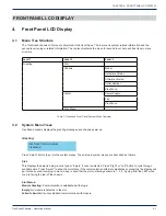
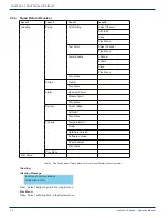
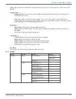
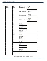
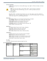
Chassis
Temperature(C)
Model
Hardware Version
Software Version
Serial Number
Prev Menu
Prev Menu
Prev Menu
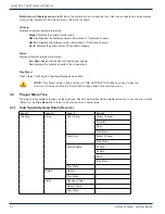
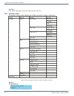
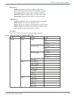
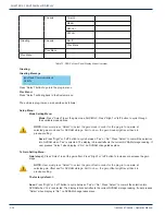
Table 7: TranScend Stacker Front Panel Display Menu Overview
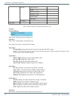
Greeting:
Greeting Message
Press “Select” button to go into the plug-in menu.
Prev Menu:
Press “Select” will bring back to the System menu.
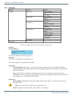
The entries in plug-in menu are described as follows:
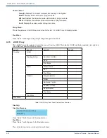
Setup Menu:
Test Point Menu:
Select the test point connection to front panel “RF TEST” output.
Sel Ch:
Press “Select” to select the channel to connect to the front panel “RF TEST” output. Press “Right” or “Left”
button to cycle through available channels.
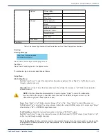
Optical Menu:
Opt Pwr (dBm):
Displays the optical power reading in dBm.
RF Level (dB)
: Displays the RF level in dB.
Attn (dB):
Displays the attenuation reading in dB.
Laser Tmp(C):
Displays the laser temperature in Centigrade.
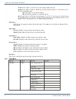
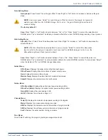
Alarm Menu:
Syn Lock:
Displays the alarm state of synthesizer lock status.
Press “Right” or “Left” button to cycle through available channels.
Opt Power:
Displays the alarm status of optical receiver power.
Laser Temp:
Displays the alarm status of laser temperature.
Module Temp:
Displays the alarm status of module temperature.
Chassis Menu:
Temp(C):
Displays the module’s temperature reading in Centigrade.
Model:
Displays the model name of plug-in module.
HW Ver:
Displays the hardware version information of plug-in module.
SW Ver:
Displays the software version information of plug-in module.
Ser #:
Displays the serial number of plug-in module.
Prev Menu:
Press “Select” will bring the plug-in’s greeting message screen back.
InnoTrans Communications
Stacker
CHAPTER 4: