LED DISPLAY
2-2
TranScend Chassis – Operation Manual
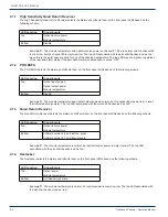
2.1.1 High Sensitivity Quad Return Receiver
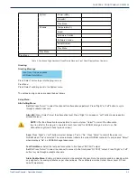
The High Sensitivity Quad Return Receiver detects the alarms and reflects them on the front panel LEDs based on the
following schema.
LED Location
Trigger Events
Top
Optical receive power
Module temperature
Bottom
Disable
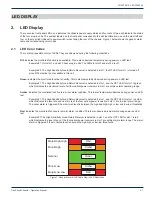
Example #1: The module temperature and optical receive power on channel #1, #2 are normal and the channel #3
is minor low, but the channel #4 is major low low. The top LED associated with the slot shall be observed as “red”,
since this is the worst case scenario for any of the observed parameters. The top LED may show green regardless
of the real-time alarm status if the per channel alarm enable switch is set as “OFF”.
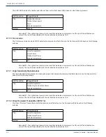
2.1.2 PON EDFA
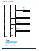
The PON EDFA detects the alarms and reflects them on the front panel LEDs based on the following schema.
LED Location
Trigger Events
Top
Optical input power
Optical output power
Module temperature
Bottom
Disable
Example #1: The module temperature and optical output power is normal, but the optical input power is at a level
that indicates a major alarm. The top LED associated with the slot shall be observed as “red”.
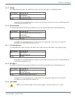
2.1.3 Quad Return Receiver
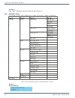
The Quad Return Receiver detects the alarms and reflects them on the front panel LEDs based on the following schema.
LED Location
Trigger Events
Top
Optical receive power
Module temperature
Bottom
Software version 2.6 and before - green
Software version 2.7 and later- disable
Example #1: The module temperature is normal, but optical receive power is major low low. The top LED
associated with the slot shall be observed as “red”.
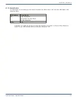
2.1.4 Destacker
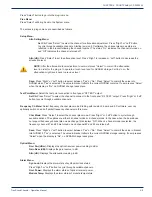
The Destacker detects the alarms and reflects them on the front panel LEDs based on the following schema.
LED Location
Trigger Events
Top
Optical power
Module temperature
Bottom
Synthesizer lock state
Example #1: The module temperature is normal, but optical power is major low low. The top LED associated with
the slot shall be observed as “red”.
CHAPTER 2:


