


SW5502C
Wireless Serial Server
User Manual
Specifications
7.1.4
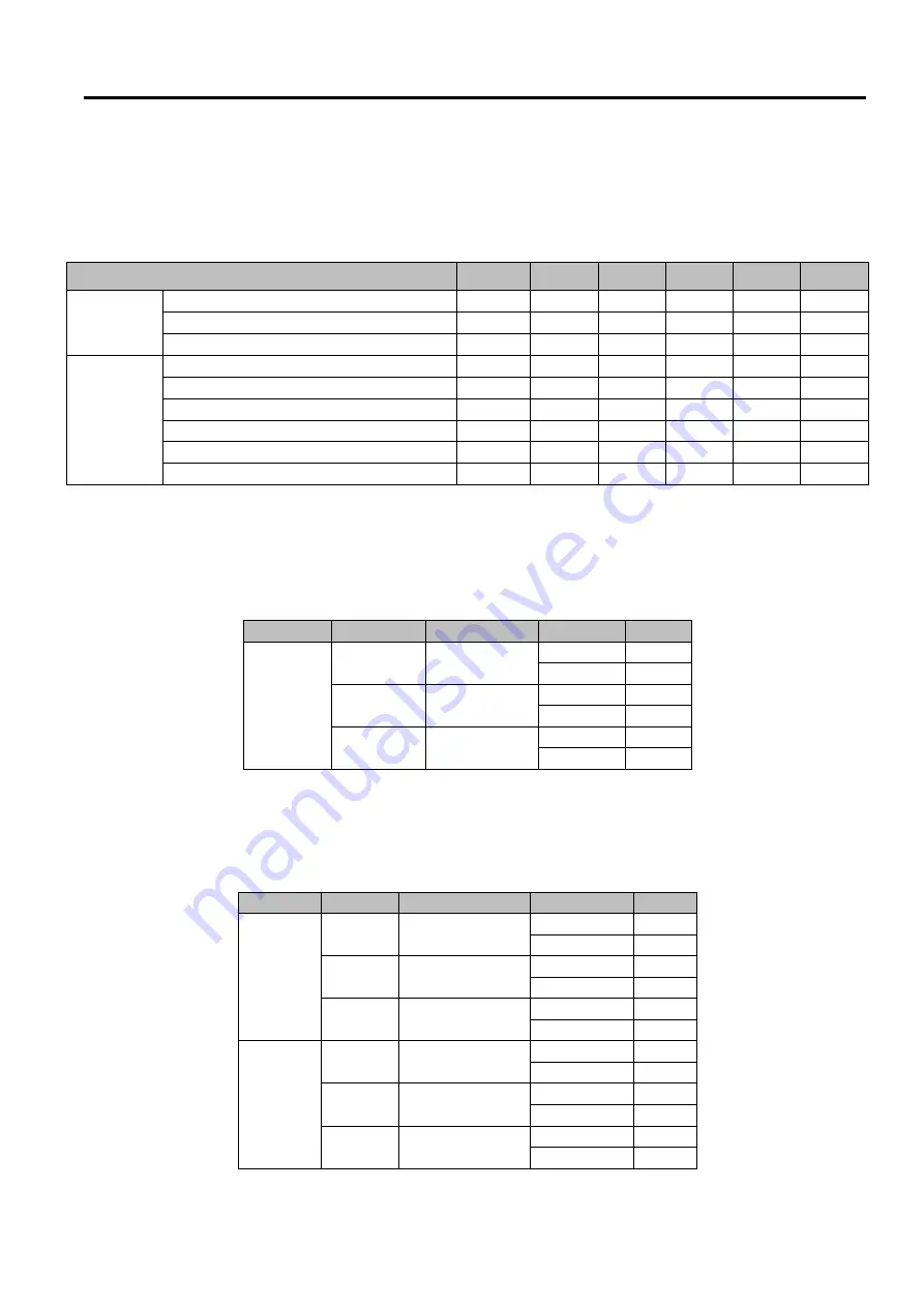
Signal LEDs
Symbols of LED
’
s Status
Table 7
.
4 Interpretation of SW550XC’s Operation
via
Front Panel LEDs
Operations
Status
LED1
LED2
LED3
LED4
LED5
Connecting
Searching for an AP
☼
☼
☼
☼
☼
☼
Cannot connected to the AP
☼
No IP provided by the DHCP Server
☼
☼
Connected
Signal Strength is less 20
%
●
Bad Signal Strength
(
20
%-
40
%)
●
●
Poor Signal Strength
(
40
%-
60
%)
●
●
●
Fair Signal Strength
(
60
%-
80
%)
●
●
●
●
Good Signal Strength
(
80
%-
94
%)
●
●
●
●
●
Excellent Signal Strength
(
95
%-
100
%)
●
●
●
●
●
●
7.1.5
Dip Switch
(
SW5501
)
Table 7
.
5 Dip Switch Functions of SW5501C
COM
Dip
Function
SW
Ω
COM1
3
Pull High
On
1K
Off
100K
2
Pull Low
On
1K
Off
100K
1
Termination
On
120
Off
0
7.1.6
Dip Switch
(
SW5502
)
Table 7
.
6 Dip Switch Function of SW5502C
COM
Dip
Function
SW
Ω
COM1
6
Pull High
On
1K
Off
100K
5
Pull Low
On
1K
Off
100K
4
Termination
On
120
Off
0
COM2
3
Pull High
On
1K
Off
100K
2
Pull Low
On
1K
Off
100K
1
Termination
On
120
Off
0
○
Off
●
On
☼
blinking


