2920 1257 04
9
Instruction book
Compressed air from the pulsation dampers will flow to
plunger (12) which causes unloading valve (UV) to open. The
air at the delivery side of the compressor is blown through
silencer (9) to atmosphere and check valve (CV) closes to
prevent venting of the pulsation dampers. The compressor
runs unloaded.
When the pressure in the pulsation dampers decreases to the
pre-set minimum pressure, the pilot valve closes. Control air
from the unloader plunger chamber is vented to atmosphere.
Unloading valve (UV) closes and compressed air is supplied
to the pulsation dampers again.
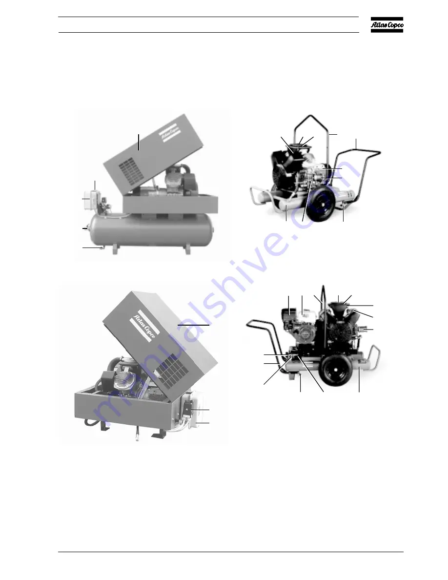
Fig. 1.13 Optional silencing hood
Fig. 1.14 Pack compressor with optional silencing hood
AV
Air outlet valve
Dm
Condensate drain valve
1
Silencing hood (standard option)
2
Electric cabinet
3
On/off switch
4
Air pressure switch with on/off switches
Figs. 1.13 and 1.14 Pack - silencing hood
Fig. 1.15 LE/LF/LT ETROL
Fig. 1.16 LE/LF/LT PETROL
AF
Air filter
AV1
Air outlet valve
Dm
Condensate drain
valve
Gp
Air pressure gauge
Me
Electric motor
Mp
Petrol motor
PD
Pulsation damper
RV
Pilot valve
UA
Unloader
1
Lifting yoke
2
Cylinder
3
Towing handle
4
Blow-off silencer
5
Cover
6
Air inlet silencer
7
Fuel tank
Figs. 1.15 and 1.16 LE/LF/LT E Trolley
1
3
2
AV
Dm
50955F
2
4
1
50956F
Mp 7 1
5
AF
6
2
4
PD
Dm
AV1
3
Gp
50958F
RV
6
5 AF
1
3
Me
4
PD UA
Dm
50957F
Summary of Contents for LE110
Page 11: ...2920 1257 04 11 Instruction book Fig 2 2 Dimension drawing LE LT55 75 and LF40 55 Power Pack ...
Page 19: ...2920 1257 04 19 Instruction book Fig 2 10 Dimension drawing LE LT15 up to 40 Unsilenced Pack ...
Page 21: ...2920 1257 04 21 Instruction book Fig 2 12 Dimension drawing LE LT15 up to 150 with CD dryer ...


