2920 1257 04
6
Instruction book
1.3.2 LE/LT40 up to -150, LF40 up to -75, each with
Y/D starter (Fig. 1.11)
The regulating system includes:
-
Electric cubicle (11)
-
Air pressure switch (MDR)
-
On/off switch (5)
-
Solenoid valve (Y1)
-
Unloader (UA) with integrated check valve (CV)
Operation
Air pressure switch (MDR) opens and closes its contacts at
pre-set pressures. During loaded operation, the contacts are
closed: the motor is running and solenoid valve (Y1) is
energized preventing the compressed air from flowing to
unloader (UA).
When the pressure in the air receiver reaches the pre-set
maximum pressure, the contacts of pressure switch (MDR)
open. The motor stops and solenoid valve (Y1) is de-
energized. Compressed air from the receiver will flow via the
solenoid valve to plunger (12) which causes unloading valve
(UV) to open. The air at the delivery side of the compressor
is blown through silencer (9) to atmosphere and check valve
(CV) closes to prevent venting of the receiver.
When the pressure in the air receiver decreases to the pre-set
minimum pressure, the contacts of the pressure switch close.
The motor restarts and, after switching over from star to delta,
solenoid valve (Y1) is energized. Control air from the unloader
plunger chamber is vented to atmosphere. Unloading valve
(UV) closes and compressed air is supplied to the receiver
again.
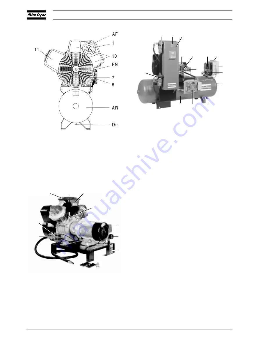
Fig. 1.7 Complete Unit, LT75 60 Hz and LT110
Fig. 1.8 Unsilenced pack
Fig. 1.9 LE/LF/LT with CD dryer
AR
AC
Dm
M
2
7
13 P1
6
Gp
AV
12
4
15
14
50954F
7
SV
AF
1
3
13
Gp
9
FC
M
50953F
D 0656
Summary of Contents for LE110
Page 11: ...2920 1257 04 11 Instruction book Fig 2 2 Dimension drawing LE LT55 75 and LF40 55 Power Pack ...
Page 19: ...2920 1257 04 19 Instruction book Fig 2 10 Dimension drawing LE LT15 up to 40 Unsilenced Pack ...
Page 21: ...2920 1257 04 21 Instruction book Fig 2 12 Dimension drawing LE LT15 up to 150 with CD dryer ...


