background image


2920 1257 04

14

Instruction book

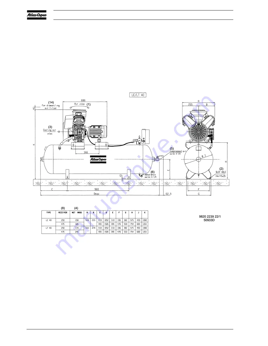
Fig. 2.5 Dimension drawing,  LE/LT40 Complete Unit (horizontal 250/475 l receiver)

Summary of Contents for LE110

Page 1: ...ght 2000 Atlas Copco Airpower n v Antwerp Belgium Any unauthorized use or copying of the contents or any part thereof is prohibited This applies in particular to trademarks model denominations part numbers and drawings This instruction book meets the requirements for instructions specified by the machinery directive 98 37 EC and is valid for CE as well as non CE labelled machines Instruction Book ...

Page 2: ...nt MDR5 6 pressure switch 39 5 6 Adjustment pilot valve on Trolley 39 5 7 Safety valve 40 5 8 Relief valve on LF55 75 LE75 up to 150 and LT 40 6 Problem solving 41 7 Principal data 42 7 1 Reference conditions 42 7 2 Limitations 42 7 3 Compressor data for LE 10 bar 42 7 3 1 50 Hz 42 7 3 2 60 Hz 43 7 4 Compressor data for LF 10 bar 43 7 4 1 50 Hz 43 7 4 2 60 Hz 44 7 5 Compressor data for LT 15 bar 4...

Page 3: ...n off switches 13 and condensate drain valve Dm For LE LF LT40 up to 75 LE LT110 150 Fig 1 6 1 7 the Power Pack mounted on an air receiver AR with air outlet valve AV pressure gauge Gp safety valve SV and condensate drain valve Dm An electric cubicle 6 includes the motor starter A separate air pressure switch 13 is provided A silencing canopy 1 Fig 1 13 is available as an option The canopy has a h...

Page 4: ...lock Power Pack When the pressure in the air receiver reaches the pre set maximum pressure the contacts as well as pressure release valve 2 are opened The motor stops the air at the delivery side of the compressor is vented to atmosphere and check valve CV closes to prevent venting of the receiver When the pressure in the air receiver decreases to the pre set minimum pressure the contacts of the a...

Page 5: ...r cap FN Fan Gp Air pressure gauge M Motor P1 Hourmeter running time SV Safety valve Y1 Loading solenoid valve 1 Cover 2 Blow off silencer 3 Air inlet silencer 4 Dewpoint indicator 5 Cooling pipe 6 Electric cabinet 7 Unloader 8 Relief valve 9 Pictograph switch off voltage and depressurize before maintenance or repair 10 LP cylinder 11 HP cylinder 12 DD filter 13 Air pressure switch with on off swi...

Page 6: ...d valve Y1 is de energized Compressed air from the receiver will flow via the solenoid valve to plunger 12 which causes unloading valve UV to open The air at the delivery side of the compressor is blown through silencer 9 to atmosphere and check valve CV closes to prevent venting of the receiver When the pressure in the air receiver decreases to the pre set minimum pressure the contacts of the pre...

Page 7: ...1 10 Air flow of LE and regulating system of LE LF LT15 up to 55 with DOL starter and separate air pressure switch Fig 1 11 Air flow of LT and regulating system of LE LT40 up to 110 LE150 and LF55 75 with Y D starter and electric cabinet ...

Page 8: ... 3 Cylinder 4 Cooler 5 On off switch 6 Cooling pipe 7 LP cylinder 8 HP cylinder 9 Blow off silencer 10 Intercooler 11 Electric cabinet 12 Plunger 13 Spring 14 Pressure regulator Figs 1 10 up to 1 12 Air flow and regulating systems 1 3 3 LE LF LTTrolley Fig 1 12 The regulating system includes Pilot valve RV Unloader UA with integrated check valve CV Electric cabinet 11 only on electric motor driven...

Page 9: ... pulsation dampers again Fig 1 13 Optional silencing hood Fig 1 14 Pack compressor with optional silencing hood AV Air outlet valve Dm Condensate drain valve 1 Silencing hood standard option 2 Electric cabinet 3 On off switch 4 Air pressure switch with on off switches Figs 1 13 and 1 14 Pack silencing hood Fig 1 15 LE LF LT ETROL Fig 1 16 LE LF LT PETROL AF Air filter AV1 Air outlet valve Dm Conde...

Page 10: ...2920 1257 04 10 Instruction book 2 Installation and handling 2 1 Dimension drawings Fig 2 1 Dimension drawing LE LT15 up to 40 and LF15 22 Power Pack ...

Page 11: ...2920 1257 04 11 Instruction book Fig 2 2 Dimension drawing LE LT55 75 and LF40 55 Power Pack ...

Page 12: ...2920 1257 04 12 Instruction book Fig 2 3 Dimension drawing LE LT15 up to 40 and LF15 22 Complete Unit horizontal 120 l receiver ...

Page 13: ...2920 1257 04 13 Instruction book Fig 2 4 Dimension drawing LT15 up to 40 Complete Unit vertical 250 l receiver ...

Page 14: ...2920 1257 04 14 Instruction book Fig 2 5 Dimension drawing LE LT40 Complete Unit horizontal 250 475 l receiver ...

Page 15: ...2920 1257 04 15 Instruction book Fig 2 6 Dimension drawing LE LT55 75 and LF40 55 Complete Unit horizontal 250 475 l receiver ...

Page 16: ...2920 1257 04 16 Instruction book Fig 2 7 Dimension drawing LE LT15 up to 40 and LF15 22 Complete Unit with optional silencing hood ...

Page 17: ...2920 1257 04 17 Instruction book Fig 2 8 Dimension drawing LE LT55 75 and LF40 55 Complete Unit with optional silencing hood ...

Page 18: ...2920 1257 04 18 Instruction book Fig 2 9 Dimension drawing LE LF LT Pack with optional silencing hood ...

Page 19: ...2920 1257 04 19 Instruction book Fig 2 10 Dimension drawing LE LT15 up to 40 Unsilenced Pack ...

Page 20: ...2920 1257 04 20 Instruction book Fig 2 11 Dimension drawing LE LT55 75 and LF40 55 Unsilenced Pack ...

Page 21: ...2920 1257 04 21 Instruction book Fig 2 12 Dimension drawing LE LT15 up to 150 with CD dryer ...

Page 22: ...2920 1257 04 22 Instruction book Fig 2 13 Dimension drawing LE LF LT Trolley with electrical motor ...

Page 23: ...2920 1257 04 23 Instruction book Fig 2 14 Dimension drawing LE LT75 up to 150 and LF75 Power Pack ...

Page 24: ...2920 1257 04 24 Instruction book Fig 2 15 Dimension drawing LE LT75 up to 150 and LF75 Complete Unit horizontal 250 475 l receiver ...

Page 25: ...2920 1257 04 25 Instruction book 2 2 Installation proposals Fig 2 16 Installation proposal for Complete Unit 120 l receiver Fig 2 17 Installation proposal for Complete Unit 250 475 l receiver ...

Page 26: ...18 Installation proposal for Complete Unit vertical 250 l receiver Fig 2 19 Installation proposal for Complete Unit with optional silencing hood Fig 2 20 Installation proposal for Pack compressors Figs 2 16 up to 2 20 Installation proposals ...

Page 27: ...lectrical installation must be carried out by an electrician and correspond to the local codes The indications on the motor data plate must correspond to the mains supply voltage and frequency The installation must include an isolating switch in the power line near to the unit and be protected against short circuits by fuses in each phase See section 2 4 The mains supply and earthing lines must be...

Page 28: ... diagram of single phase LE LF LT with direct on line starter Fig 2 23 Electrical diagram of 3 phase LE LF LT15 up to 55 with direct on line starter Fig 2 24 Electrical diagram of 3 phase LE LT40 up to 110 LE150 and LF40 up to 75 with star delta starter ...

Page 29: ...g 2 25 Electrical diagram of 3 phase LE LT40 up to 110 LE150 and LF40 up to 75 with transformer and star delta starter Fig 2 26 Electrical diagram of 3 phase LE LT40 up to 110 LE150 and LF40 up to 75 with star delta starter and CD dryer ...

Page 30: ... LE LF LT22 400 5 6 10 LE LF LT40 230 15 7 25 LE LF LT40 400 9 3 16 LE LF LT55 230 20 3 25 LE LF LT55 400 12 0 25 LT75 400 14 7 63 60 Hz Type Voltage Overload relay Fuses V A A LE LT15 230 1 phase 11 7 16 LE LT15 230 460 4 5 10 LE15 380 4 7 10 LE LF LT15 440 460 4 1 10 LE LT22 230 1 phase 17 9 25 LT22 20 bar 230 3 phase 11 1 16 LE LT22 230 460 7 6 10 LE LF LT22 440 460 5 7 10 LE LF LT40 230 1 phas...

Page 31: ...E LF LT75 230 14 5 40 LE LF LT75 400 8 5 25 LE LF75 440 7 8 25 LE LF LT75 500 6 9 25 LE LT110 230 22 5 63 LE LT110 400 13 1 40 LE LT150 400 16 2 40 60 Hz Type Voltage Overload relay Fuses V A A LE LT40 230 11 8 25 LE LT40 380 6 9 25 LE LT40 440 460 5 5 16 LT40 575 4 7 16 LE LF LT55 230 14 4 40 LE LF LT55 380 8 5 25 LE LF55 400 7 2 25 LE LF LT55 440 460 7 2 25 LF LT 75 230 18 2 63 LE LF LT 75 380 1...

Page 32: ...rect direction of rotation as indicated by the arrow on the fan housing If the rotation direction is wrong switch off the voltage and reverse two of the input line connections 6 Check the operation of the air pressure switch See section 5 4 or 5 5 Check the operation of pilot valve RV on LE LF LT Trolley See section 5 6 3 2 Starting LE LF LT 1 On LE LT check the oil level which must be near the to...

Page 33: ...Regularly drain condensate Dm Fig 1 16 3 3 Stopping LE LF LT 1 On compressors with DOL starter push the 0 button on top of the pressure switch On compressors with Y D starter push switch S1 Fig 2 21 to position 0 2 Close air outlet valve AV Figs 1 4 1 6 3 Switch off the voltage If a compressor with pressure switch with pressure release valve stops during operation through a power failure the press...

Page 34: ... and if provided also relief valve 4 4 5 3 3 4 2 Inspect air filter Yearly 500 4 4 5 3 3 4 2 On LF75 LE LT110 and LE150 replace air filter 600 4 4 5 3 3 4 2 On LE LT40 up to 75 and LF40 55 replace air filter 800 4 4 5 3 3 4 2 On LE LF LT15 22 replace air filter 2000 2 Change blow off silencer if provided 2000 4 3 On LE LT if mineral oil is used change oil 2 yearly 3000 4 3 5 On LE LT if Atlas Copc...

Page 35: ...or Ordering Ref on unloader UA number Fig 4 1 For LE LF LT40 up to 75 1503 6176 60 4 Service kit for Ordering Ref on check valve CV number Fig 4 1 For all LE LF LT40 up to 150 1503 6177 60 3 Service kit for Ordering Ref on valve discs number Fig 4 1 For LE15 up to 40 and LF15 22 1503 5800 60 1 For LE55 LE75 50 Hz and LF40 1503 5800 61 1 For LT15 up to 40 1503 5800 62 1 For LT55 LT75 50 Hz and LF55...

Page 36: ...ve discs O rings and joints when the cylinder heads are disassembled Replacement of valve discs Figs 5 1 and 5 2 LE15 55 LE75 60 Hz Operation sequence LE75 50 Hz HP cylinder LF15 40 LE110 150 LE75 60 Hz HP cylinder LP cylinder LT15 110 LE110 150 HP cylinder LP cylinder LF55 75 LT15 110 HP cylinder LP cylinder LF55 75 LP cylinder Remove the fan guard unscrew the cap and remove the cover 1 Fig 1 1 a...

Page 37: ...top the compressor 2 On LE LF LT 15 up to 55 and LE LT75 50 Hz unscrew the cap on top of cover 1 Fig 1 1 Lift off the cover and filter element Take care that no dirt drops inside the suction silencer On LE LT75 60 Hz LF75 LT110 and LE110 150 unscrew cap 1 Fig 1 7 and take out the air filter Take care that no dirt drops inside the suction silencer 3 Using a damp cloth clean the filter chamber and c...

Page 38: ...ce diagrams MDR4 11 bar and MDR4 25 bar Example LE Stopping pressure 7 bar e Starting pressure adjustable between 3 and 5 7 bar e 1 Air pressure switch 2 Solenoid valve 3 Pressure release valve 4 Adjusting screw stopping pressure 5 Adjusting screw pressure difference Figs 5 3 up to 5 5 Air pressure switch 1 2 3 50960F 4 5 50961F ...

Page 39: ... by means of pilot valve RV Fig 1 16 The valve also controls the difference between the preset maximum pressure and that at which compression is resumed Unload mechanism The pilot valve is equipped with a hand operated unload mechanism by turning the red handle 1 90 degrees the plunger of the valve will be lifted releasing the spring force The air pressure from the pulsation dampers will force dow...

Page 40: ...7 it must be replaced by a new one If the compressor unloads before the specified opening pressure is reached repeat the procedure as mentioned from step 3 6 Readjust the unloading pressure as described in sections 5 4 and 5 5 7 Reconnect the hose or pipe to the closed air outlet valve Testing on LE LF LT Trolley 1 Close the air outlet valves depressurize and disconnect the hoses from the valves 2...

Page 41: ...t hold pressure a Check valve leaks a Check for broken valve and springs b Air leaks b Check and correct as necessary 6 Too frequent starting too short operating periods a Air pressure switch or pilot valve 1 incorrectly set a Increase pressure difference b Check valve leaks b See 5a 7 High oil consumption on LE LT compressors a Oil level too high a Do not overfill crankcase Keep level in red circ...

Page 42: ...10 10 Maximum working pressure for LE Trolley bar e 9 5 9 5 9 5 9 5 9 5 9 5 9 5 Pre set pressure difference for LE Trolley bar 1 1 1 1 1 1 1 Temperature at outlet valve approx Unsilenced compressor Celsius 40 44 66 59 80 65 91 Silenced compressor Celsius 48 52 74 67 88 73 99 Power input at max working pressure kW 1 82 2 54 4 57 6 11 8 28 10 69 14 92 Motor shaft speed r min 1500 1500 1500 1500 1500...

Page 43: ...ound pressure level 1 Standard version dB A 80 81 81 82 83 84 85 Silenced receiver mounted version dB A 67 68 68 72 74 75 75 Silenced pack version dB A 65 66 66 70 70 72 73 7 4 Compressor data for LF 10 bar 7 4 1 50 Hz Compressor type LF15 LF22 LF40 LF55 LF75 Maximum working pressure for LF bar e 10 10 10 10 10 Maximum working pressure for LF Trolley bar e 9 5 9 5 9 5 9 5 9 5 Pre set pressure diff...

Page 44: ...on dB A 69 70 70 74 76 7 5 Compressor data for LT 15 bar 7 5 1 50 Hz Compressor type LT15 LT22 LT40 LT55 LT75 LT110 Maximum working pressure for LT bar e 15 15 15 15 15 15 Maximum working pressure for LT Trolley bar e 13 7 13 7 13 7 13 7 13 7 13 7 Pre set pressure difference for LT Trolley bar 1 1 1 1 1 1 Temperature at outlet valve approx Unsilenced compressor Celsius 49 57 68 56 75 72 Silenced c...

Page 45: ... 6 5 6 5 6 5 6 5 Maximum sound pressure level 1 Standard version dB A 80 81 81 82 83 84 Silenced receiver mounted version dB A 67 68 68 72 73 74 Silenced pack version dB A 65 66 66 70 71 72 7 6 Compressor data for LT 20 bar 7 6 1 50 Hz Compressor type LT15 LT22 LT40 LT55 LT75 LT110 LT150 Maximum working pressure bar e 20 20 20 20 20 20 20 Temperature at outlet valve approx Unsilenced compressor Ce...

Page 46: ... 5 6 5 6 5 6 5 Maximum sound pressure level 1 Standard version dB A 80 81 81 82 83 84 85 Silenced receiver mounted version dB A 67 68 68 72 72 75 75 Silenced pack version dB A 65 66 66 70 70 72 72 7 7 Compressor data for LT 30 bar 7 7 1 50 Hz Compressor type LT22 LT40 LT55 LT75 Maximum working pressure bar e 30 30 30 30 Temperature at outlet valve approx Unsilenced compressor Celsius 49 60 42 58 S...

Page 47: ...or Celsius 61 73 57 Power input at max working pressure kW 3 44 5 77 7 63 Motor shaft speed r min 1800 1800 1800 Free air delivery 2 l s 3 1 5 5 8 0 Oil capacity l 0 8 0 8 1 4 Opening pressure of relief valve bar e 6 5 6 5 6 5 Maximum sound pressure level 1 Standard version dB A 81 81 82 Silenced pack version dB A 66 66 70 Footnotes chapter 7 1 According to CAGI PNEUROP PN8NTC2 2 2 At reference co...

Page 48: ...le h 1 kW 1 341 hp UK and US 1 l 0 264 US gal 1 l 0 220 Imp gal UK 1 l 0 035 cu ft 1 m 3 281 ft 1 mm 0 039 in 1 m 3 min 35 315 cfm 1 mbar 0 401 in wc 1 N 0 225 lbf 1 Nm 0 738 lbf ft x degrees celsius 32 1 8 x degrees fahrenheit 1 Footnote chapter 8 1 A temperature difference of 1 degree celsius a temperature difference of 1 8 degrees fahrenheit ...

Reviews: