2920 1257 04
32
Instruction book
2.4.3 Cable size
Type
Starter
Cable size (mm
2
)
LE/LF/LT15/22
DOL
2.5
LE/LF/LT40/55
DOL
4
LT75
DOL
6
LE/LT40
Y/D
2.5
LE/LF/LT55
Y/D
4
LE/LF/LT75
Y/D
6
LE/LT110
Y/D
6
LE/LT150
Y/D
10
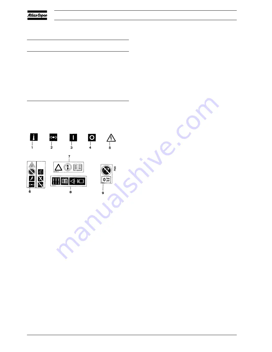
2.5 Pictographs
3 Operating instructions
Safety precautions
The operator must apply all relevant safety precautions,
including those mentioned in this book.
3.1 Initial start-up
If the compressor has not run for the past 6 months (at initial
start-up check the date on the data plate), it is strongly
recommended to improve the lubrication of the compressor
element: drain the oil, refill the compressor with the same oil
while turning the crankshaft.
Note: It is strongly recommended to install an interstage drain
kit, to remove excess condensate, on LT compressors with a
load factor less than 20% per hour. Consult Atlas Copco.
1. For Complete Units, remove the transport brackets from
underneath the compressor.
2. Check the electrical installation, which must be in
accordance with the instructions given in section 2.3.
3. LE/LT are filled with PAO (polyalphaolefine) compressor
oil. Check that the oil level is still near the top of the red
circle of sight-glass (SG-Fig. 1.3). Top up, if necessary.
4. Switch on the voltage. Start the motor.
5. On three-cylinder compressors, check for correct direction
of rotation as indicated by the arrow on the fan housing. If
the rotation direction is wrong, switch off the voltage and
reverse two of the input line connections.
6. Check the operation of the air pressure switch. See section
5.4 or 5.5. Check the operation of pilot valve (RV) on LE/
LF/LT Trolley. See section 5.6.
3.2 Starting
LE/LF/LT
1. On LE/LT, check the oil level, which must be near the top
of the red circle of sight-glass (SG-Fig. 1.3). The minimum
level is the lower part of the red circle.
2. Switch on the voltage.
3. On compressors with DOL starter, push the (I) button
on top of the pressure switch.
On compressors with Y-D starter, push switch (S1-Fig.
2.21) to position (I)
4. Open the air outlet valve (AV-Figs. 1.4/1.6).
5. Regularly drain condensate (Dm-Figs. 1.4/1.7).
LE/LF/LT Trolley with electrical motor
1. On LE/LT, check the oil level, which must be near the top
of the red circle of sight-glass (SG-Fig. 1.3). The minimum
level is the lower part of the red circle.
2. Set pilot valve (RV-Fig. 1.12) in the unload position by
turning the red handle 90 degrees (see section 5.6).
3. Attach the air lines to the air outlets.
4. Plug in and switch on the voltage at the main circuit breaker.
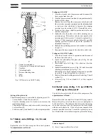
1
Temperature
2
Pressure
3
On
4
Off
5
Warning: voltage
6
Switch off voltage and depressurize before maintenance
or repair
7
Read Instruction book before starting
8
Consult Instruction book for correct direction of
rotation
9
Do not adjust switch if it is depressurized
Fig. 2.27 Pictographs (typical examples)
Summary of Contents for LE110
Page 11: ...2920 1257 04 11 Instruction book Fig 2 2 Dimension drawing LE LT55 75 and LF40 55 Power Pack ...
Page 19: ...2920 1257 04 19 Instruction book Fig 2 10 Dimension drawing LE LT15 up to 40 Unsilenced Pack ...
Page 21: ...2920 1257 04 21 Instruction book Fig 2 12 Dimension drawing LE LT15 up to 150 with CD dryer ...


