


BERT Technical Articles
GB1400 User Manual
B-23
Clock
Source
Data
Source
Driver
System
under test
Line
receiver
Clock
recovery
Decision
circuit
Jitter
measurement
Clock
recovery
Error
monitor
Data pattern
generator
Error
monitor
Data pattern
generator
Data pattern
generator
Clock
Source
Clock
Source
Data
Source
Driver
System
under test
Line
receiver
Clock
recovery
Decision
circuit
Jitter
generator
Data pattern
generator
(a)
(b)
BERT
transmitter
BERT
transmitter
BERT
receiver
BERT
receiver
C
D’
F
H
G
H
G
F
D’
C’
H’
G’
G’
H’
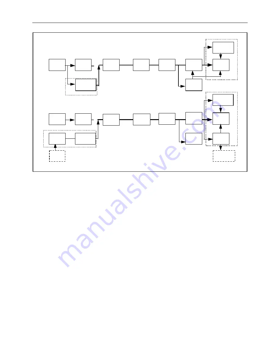
Figure 2. In the simplest use of a bit-error-rate tester, the instrument creates a known data signal,
D'. At the receive end, the BERT duplicates that signal so it can compared with the transmitted
version (see flowchart a).
In some cases, the BERT may supply the system clock signal and even add a known jitter that can
be measured at the receive end (see flowchart b). If the BERT supplies the clock, the instrument's
clock source and clock recovery-circuit must be at least as good as their counterparts in the
system under test.
Supplying Data Patterns
To monitor the transmission, the BERT receiver generates its own data pattern, H
′
, which is the same as
the desired data, D
′
. The BERT receiver compares the received signal, H, with H
′
, and looks for errors.
The tester records the total number of errors, the ratio of errors to bits (the bit error rate), the number of
“errored” seconds (ES), and the ratio of ES to total seconds.
To make a valid comparison, the BERT receiver must synchronize H
′
with H. Accomplishing
synchronization depends on whether the data is a fixed or psuedorandom pattern.
Sometimes it is convenient for the BERT to supply its own clock signals for its transmitter and/or its
receiver. For instance, the system clock may be unavailable in a field situation, or the test engineer may
want to avoid the trouble of providing and phasing the clock at the BERT receiver. In this case, the
BERT’s transmitter clock is C
′
, and its receiver clock is G
′
(see the figure above for reference). In
laboratory applications, it is common for the BERT to provide a wide range of clock frequencies.
The BERT’s clock source and clock-recovery circuit must be as good as their counterparts in the system
under test. The source must introduce negligible time jitter, because phase jitter in C
′
causes phase jitter in
the recovered clock signal, G, relative to the received data signal, F.
Summary of Contents for gigaBERT1400
Page 16: ...Preface GB1400 User Manual xvi ...
Page 17: ...Getting Started ...
Page 26: ...Operating Basics ...
Page 66: ...Application Note Auto Search Synchronization 2 40 GB1400 User Manual ...
Page 76: ...Application Example 2 50 GB1400 User Manual ...
Page 77: ...Reference ...
Page 163: ...Reference 3 86 GB1400 User Manual ...
Page 164: ...Appendices ...
Page 174: ...Specifications A 10 GB1400 User Manual ...
Page 194: ...BERT Technical Articles B 20 GB1400 User Manual ...
Page 320: ...Remote Commands C 102 GB1400 User Manual ...
Page 332: ...Using GPIB RS 232 D 12 GB1400 User Manual ...
Page 341: ...Performance Verification GB1400 Acceptance Test E 9 ...
Page 349: ...Default Settings F 6 GB1400 User Manual MISC View Angle 0 Panel Lock OFF Response Header ON ...
Page 351: ...Cleaning Instructions G 2 GB1400 User Manual ...
Page 368: ...Glossary Index ...


