2-14
Chapter 2: Basic installation
Chapter 2
•
The plugged USB 3.0 device may run on xHCI mode or EHCI mode, depending on the
operating system’s setting.
•
Only USB 3.1 ports E12 support Ai function.
•
Only USB 2.0 port 8 supports USB function.
•
USB 3.0 devices can only be used as data storage only.
•
We strongly recommend that you connect USB 3.0 devices to USB 3.0 ports for faster
and better performance for your USB 3.0 devices.
•
Due to the design of the Intel
®
X99 series chipset, all USB devices connected to the
USB 2.0 and USB 3.0 ports are controlled by the xHCI controller. Some legacy USB
devices must update their firmware for better compatibility.
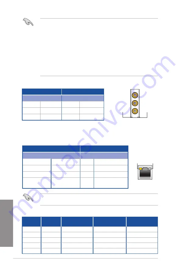
* LAN ports LED indications
ACT/LINK
LED
SPEED
LED
LAN port
Activity Link LED
Speed LED
Status
Description
Status Description
Off
No link
Off
10 Mbps connection
Orange
Linked
Orange 100 Mbps connection
Orange (Blinking)
Data activity
Green
1 Gbps connection
Orange (Blinking
then steady)
Ready to wake up
from S5 mode
You can disable the LAN controllers in BIOS. Due to hardware design, the LAN1 port’s
LEDs may continue to blink even when disabled.
** Audio 2, 4, 6, or 8-channel configuration
Port
Headset
2-channel
4-channel
6-channel
8-channel
Light Blue
Line In
Line In
Line In
Side Speaker Out
Lime
Line Out
Front Speaker Out
Front Speaker Out
Front Speaker Out
Pink
Mic In
Mic In
Mic In
Mic In
Orange
–
–
Center/Subwoofer
Center/Subwoofer
Black
–
Rear Speaker Out
Rear Speaker Out
Rear Speaker Out
*Bluetooth and Wi-Fi module LED indications
Wi-Fi 802.11 a/b/g/n/ac,
Bluetooth v4.0
Wi-Fi LED
Bluetooth LED
Status
Description Status
Description
Off
No link
Off
No link
Green
Linked
Blue
Linked
Blinking
Data activity
Wi-Fi
LED
Bluetooth
LED
* The Bluetooth word mark and logos are owned by Bluetooth SIG, Inc. and any use of such mark by ASUSTeK
Computer Inc. is under license. Other trademarks and trade names are those of their respective owners.
Summary of Contents for X99-M WS
Page 1: ...Motherboard X99 M WS ...
Page 53: ...ASUS X99 M WS 2 5 Chapter 2 To install the CPU heatsink and fan assembly ...
Page 54: ...2 6 Chapter 2 Basic installation Chapter 2 To remove a DIMM 2 1 4 DIMM installation ...
Page 55: ...ASUS X99 M WS 2 7 Chapter 2 2 1 5 ATX Power connection OR OR ...
Page 56: ...2 8 Chapter 2 Basic installation Chapter 2 2 1 6 SATA device connection OR ...
Page 132: ...3 66 Chapter 3 BIOS setup Chapter 3 ...
Page 152: ...4 20 Chapter 4 Software support Chapter 4 ...
Page 170: ...A 2 Appendices Appendices X99 M WS block diagram ...


