1-3
ASUS P3-P5G31
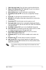
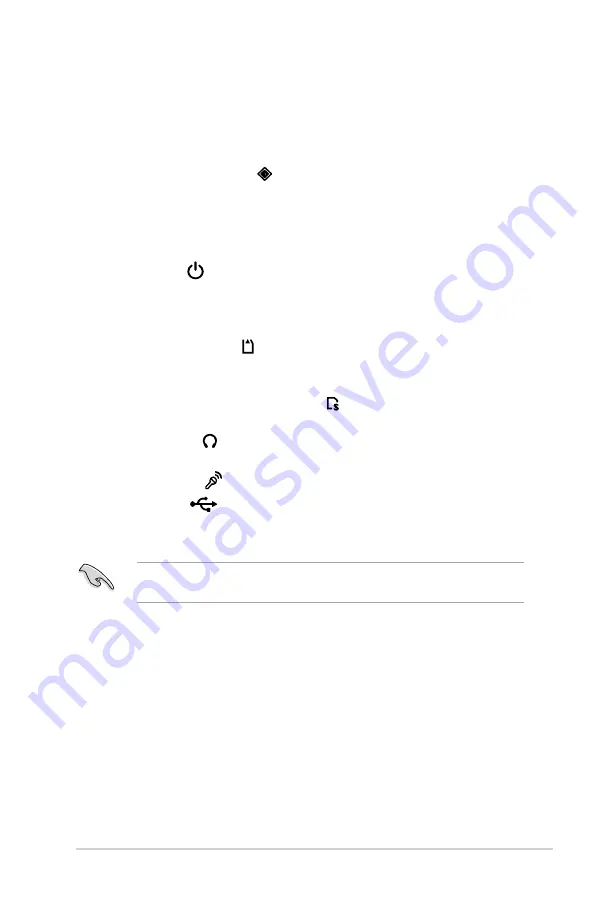
1. Optical drive eject button.
Press this button to eject the optical drive tray.
2. Memory Stick
®
/Memory Stick Pro™ card slot*
. This slot is for a Memory
Stick
®
/Memory Stick Pro™ storage card.
3. Optical drive/bay cover.
Covers the optical drive or optical drive bay.
4. CompactFlash
®
card slot* .
This slot is for a CompactFlash
®
storage
card.
5. Power LED.
This LED lights up to indicate that the system is ON.
6. HDD LED.
This LED lights up when data is being read from or written to the
hard disk drive.
7. Power button .
Press this button to turn the system on or off.
8. Front panel cover.
Covers the 6-in-1 card reader and front panel I/O ports.
Press the indicated area to open the front panel cover. Refer to the illustration
in the previous page.
9. SmartMedia
®
card slot* .
This slot is for a SmartMedia
®
storage card.
10. Card reader LED.
This LED lights up when data is being read from or written
to a storage card inserted in any of the card reader slots.
11. Secure Digital™/MultimediaCard slot* .
This slot is for a Secure
Digital™/MultimediaCard storage card.
12. Headphone port .
This port connects a headphone with a stereo mini-
plug.
13. Microphone port .
This Mic (pink) port connects a microphone.
14. USB 2.0 ports
.
These Universal Serial Bus 2.0 (USB 2.0) ports are
available for connecting USB 2.0 devices such as a mouse, printer, scanner,
camera, PDA, and others.
* Use and format a storage card according to the documentation that comes
with it.
Summary of Contents for P3-P5G31
Page 52: ...3 Chapter 3 Getting started ...

