


1-4
Chapter 1: System introduction
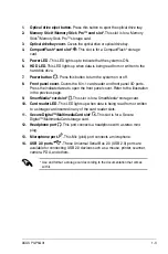
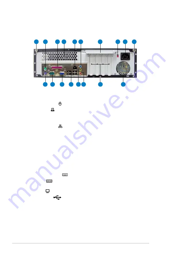
1. Cover screw.
Secures the system cover.
2. PS/2 mouse port .
This green 6-pin connector is for a PS/2 mouse.
3. Parallel port .
This 25-pin port connects a printer, scanner, or other
devices.
4. Air vent.
Provides ventilation for the system.
5. LAN (RJ-45) port .
This port allows Fast Ethernet connection to a Local
Area Network (LAN) through a network hub.
6. Line In port (light blue).
This port connects a tape, CD, DVD player, or other
audio sources.
7. Metal bracket lock.
Secures the expansion slot/card metal brackets.
8. Voltage selector.
Allows you to adjust the system input voltage according to
the voltage supply in your area. See the section
2.12 Selecting the voltage
before adjusting this switch.
9. Power connector.
Connects the power cable and plug.
10. PS/2 keyboard port .
This purple 6-pin connector is for a PS/2 keyboard.
11. COM port
.
This port connects a mouse, modem, or other devices that
confoms with serial specification.
12. VGA port .
Connects a VGA monitor.
13. USB 2.0 ports
.
These Universal Serial Bus 2.0 (USB 2.0) ports are
available for connecting USB 2.0 devices such as a mouse, printer, scanner,
camera, PDA, and others.
14. Line Out port (lime).
This port connects a headphone or a speaker. In
4-channel, and 6-channel configuration, the function of this port becomes
Front Speaker Out.
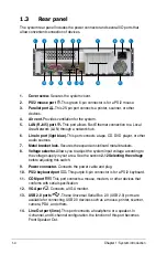
1.3
Rear panel
The system rear panel includes the power connector and several I/O ports that
allow convenient connection of devices.
1
10
11
12
13 14 15
16
17
8
9
7
6
5
4
3
2
1
Summary of Contents for P3-P5G31
Page 52: ...3 Chapter 3 Getting started ...