-
40 -
Model 12-1015 Users’ Manual Version 13.08
Associated Equipment Corp.
5043 Farlin Ave.
800-949-1472(US)
St. Louis, MO 63115
314-385-5178 (Outside US)
11.0 – Alternator Test
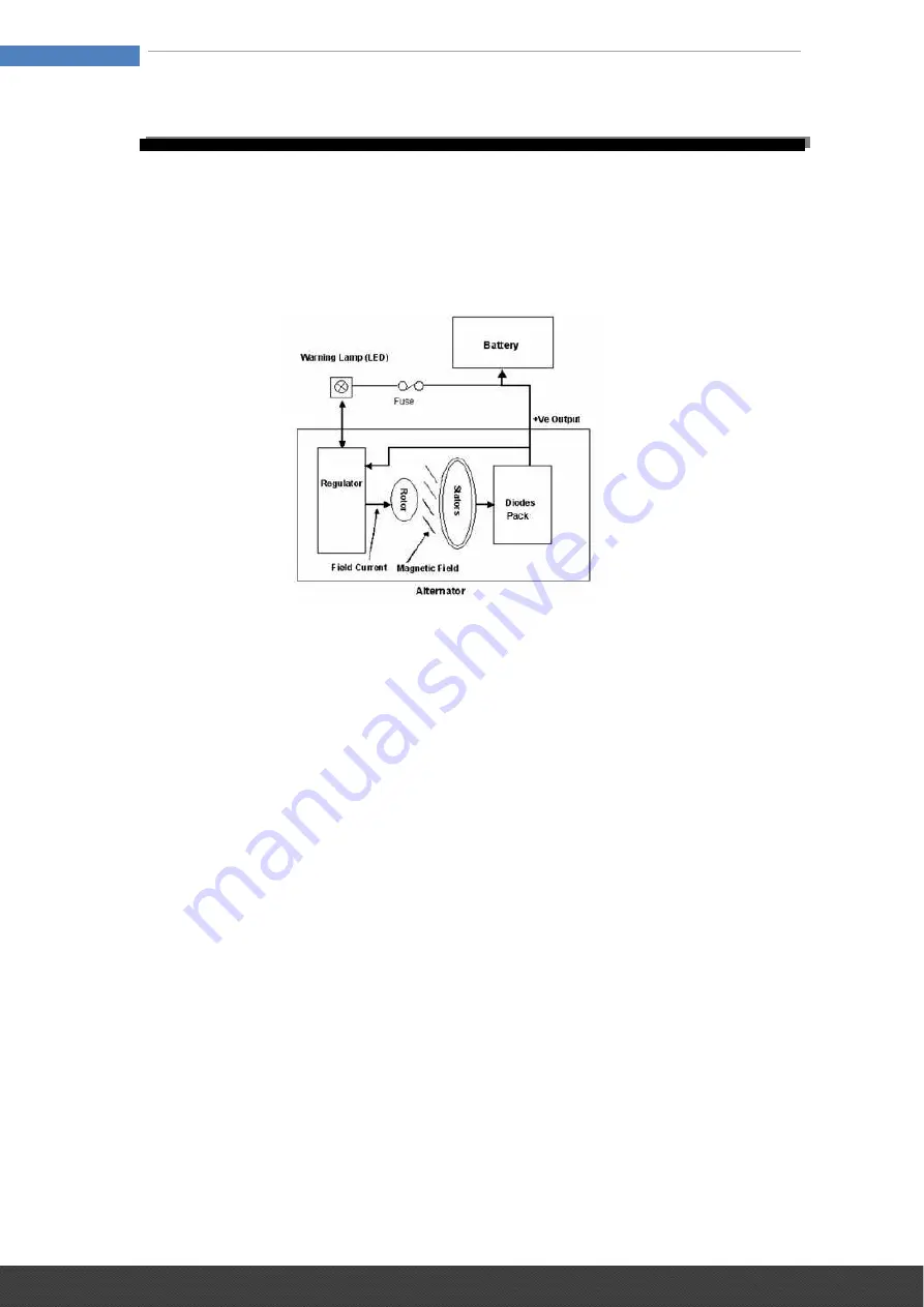
An alternator is the device used to produce the electricity the car needs to
run and to keep the battery charged. The alternator uses the principle of
electromagnetic induction to produce voltage and current. The four main
parts of the alternator are the Rotor, Stator, Diode Pack, Voltage Regulator
and an Ammeter or Indicator Light to inform the driver of any problems. All of
these parts must be in good working order for the alternator to do its job.
The Rotor is a coil of wire wound around an iron core. The Rotor rotates as
the alternator shaft rotates and current passes through brushes. The Rotor
winding passes the Field current. This causes the Rotor to produce a
magnetic field. So basically the Rotor is a rotating electro magnet.
The Stator is a set of three windings fixed to the case of the alternator and
these windings are static i.e. they don’t rotate. As the Rotor rotates its
magnetic field “cuts” each Stator winding in turn, this induces a current in
each winding. The outputs from the Stator windings are 120 degrees apart
and are alternating current (AC).
But vehicles run on DC current, so we need something that will convert the
AC current to DC current. This is the job of the diode pack. A diode is an
electrical one-way check valve that will let current flow in only one direction.
The typical diode pack uses four diodes to accomplish this. AC current is
feed in on one side of the diode pack and DC current comes out the other
side. The diode pack here will rectify the alternating 3 phases from the
Stators and combine them into a single Direct Current which also works the
dash ammeter or indicator light.
Now that we have a DC current that the vehicle can use, we need a way to
control that current. That is the job of the voltage regulator. As the name
implies, it regulates the voltage going to the battery. It does this by turning
current to the field (stator) terminal of the alternator on and off.
If the battery voltage goes below 13.5 volts, the voltage regulator sends
current to the field terminal and allows the alternator to start charging.
Current will then flow into the battery and bring it up to full charge.
If the voltage goes above 15.0 volts, the voltage regulator shuts off the
current to the field terminal and keeps the battery from overcharging and
cooking itself. This is how the voltage regulator controls the alternator output.


