page 11
# 62 80
8 -3 2 x 1 /2
a lu minu m
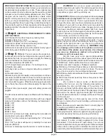
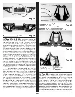
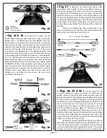
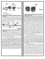
Fig. 25
❏
Fig. 26
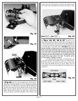
Now remove the #7301 truck black hard
anodized aluminum chassis from the kit box.
Note: If you are
familiar with our products you will see that this is a new
chassis design using our new aircraft aluminum alloy. The
chassis has been engineered to improve the rigidity of the
chassis for both front to rear and side to side. It also features
improved chassis side roll clearance for rougher tracks.
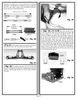
Fig. 26
❏
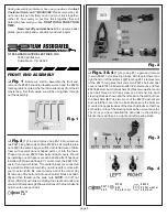
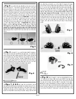
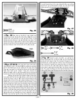
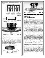
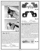
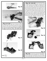
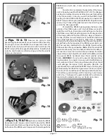
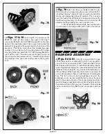
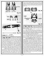
Figs. 27 & 28
(1) From bag #7-4 remove the silver
colored #6931 8-32 x 1/4" steel FHMScrew (this screw is also
part of the #7306 servo saver replacement screw set). (2)
Now open up bag #7-2 and remove the two #7306 special
black steel servo saver screws. These two screws are
different lengths, with a short threaded shank by the screw
head, a smooth center shaft and then a smaller threaded end.
(3) Now line up the #7305 black anodized aluminum
nose plate with the front end assembly over the front of the
chassis as shown in fig. 27. (4) There are three holes in the
chassis and six holes in the nose plate. Starting with the 1/4"
FHMScrew we are going to install it from the bottom of the
chassis using the center hole of the chassis holes and thread
it into the forward center hole of the nose plate. Do not tighten
this screw completely just yet. (5)Now install the longer of the
#7306 screws into the left front hole of the chassis (from the
bottom). It will then thread into the left forward hole of the nose
plate if you have everything lined up correctly. Again do not
tighten this screw yet. (6) Now you can install the shorter
#7306 screw into the right front hole of the chassis and into
the right forward hole of the nose plate. (7) When everything
looks lined up and threaded correctly you can then finish
tightening up the three screws as shown in fig. 28.
Fig. 27
# 6931
8 -32 x 1 /4
s te el
# 7306
7 /8
s pe cia l
Fig. 28
#7306
1 3/8
spe cia l
❏
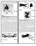
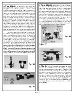
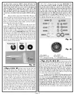
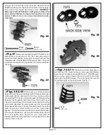
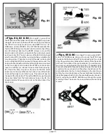
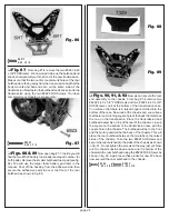
Fig. 29
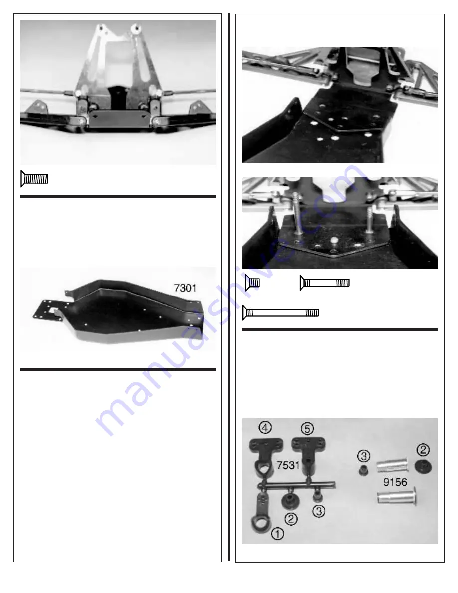
Inside the same bag #7-2 you will find the
#7531 black plastic servo saver parts tree and the #9156
aluminum servo saver tube. The names of the parts on the
parts tree are: (1) left upper servo saver arm, (2) lower servo
saver bushing, (3) upper servo saver bushing, (4) left lower
servo saver arm, (5) right side bellcrank. Remove the two
servo saver bushings and install them into the servo saver
tube. The upper bushing goes into the threaded end of the
tube and the lower bushing goes into the hex end of the tube.
Fig. 29


