page 8
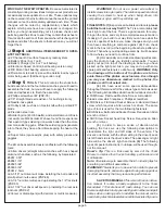
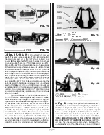
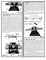
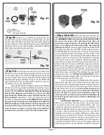
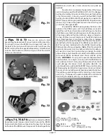
set screws onto the .050 Allen wrench and carefully thread
the set screw into the back of the front axle until it tightens
down on the kingpin as shown in fig. 9. (5) Do the same with
the other axle assembly.
Fig. 10
❏
Figs. 11, 12 & 13
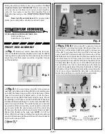
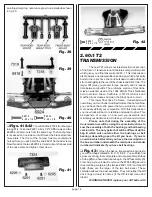
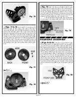
Remove the bag containing
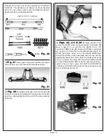
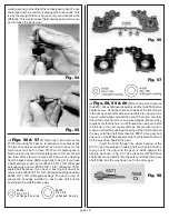
the front and rear suspension arms. From this bag remove
the two #7206 front suspension arms as shown in fig. 11. This
photo shows you which arm is right (passenger side) and
which is left (driver’s side). It also shows you where to trim the
runners from the arms.
(1) Use your pliers to remove the runners from both
A-arms. (2) Use your hobby knife to remove any part of the
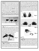
runners remaining on the suspension arms. (3) From bag #7-
1 locate the two #6227 outer hinge pins (match them against
the scale drawing). Install one of the hinge pins through the
holes in the outside end of the A-arm, hold the pin, and see
if the arm will swing freely on the pin. (4) Using the same pin,
check the fit in the #6210 left front block carrier. We want the
pin to fit tight in the hole. (5) Now remove the outer hinge pin
and install the left block carrier assembly into the left outer A-
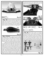
arm location using the #6227 hinge pin. (6) Install a #6299 1/
8" E-clip on each end of the hinge pin. The ball ends will both
be on the back (or straight) side of the A-arm when installed
correctly. The #6210 block carrier will be angled towards the
front as shown in fig. 13. (6) Now repeat the above steps for
the right side A-arm. It will be a mirror image of the left.
Fig. 11
#62 99
e-c lip
1/8 sh aft
Fig. 12
Fig. 13
❏
Figs. 14, 15 & 16
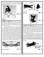
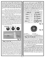
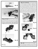
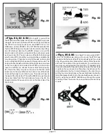
Go back to bag #7-1 and
remove the #7207 front bulkhead, the #7208 front bulkhead
aluminum support, and the two #7209 front inner hinge pins.
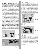
Match the hinge pins to the scale drawing. Fig. 14 shows you
the front bulkhead alone to make it easier to identify the front
and back sides of the bulkhead. Check the fit of the #7209
hinge pins in the A-arms the same way we did in fig. 12. Free
them up if necessary. We want the pins to be tight in the front
bulkhead but free in the arms.
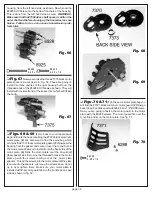
(1) Starting with the left A-arm, install the inner hinge
pin from the back side through the back half of the A-arm and
the #7207 front bulkhead. (2) Now line up the #7208 alumi-
num bulkhead support between the front side of the bulkhead
and the front of the left A-arm. Push the hinge pin the rest of
the way through. (3) Secure the hinge pin with a #6299 E-clip
on each end. (4)Now assemble the right side suspension the
same way. Fig. 16 shows the front bulkhead assembly
completed.
Fig. 14


