


page 38
Fig. 149
Fig. 150
❏
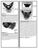
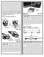
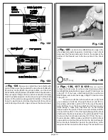
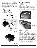
Fig. 151 & 152
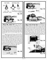
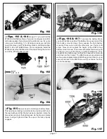
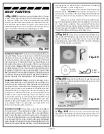
In bag #7-7 you will find the #7327
front battery mount for the T2, two #6916 4-40 x 1/2"
SHCScrews (with hole) and two #6292 4-40 x 3/8"
FHSScrews. Thread the #6916 screws into the front battery
mount as shown. We will adjust the height of the #6916
screws a little later in the instructions. Referring to fig. 152,
use the two #6292 FHSScrews to fasten the front battery
mount to the chassis.
# 6292
4 -40 x 3 /8
# 69 16
4 -4 0 x 1 /2
Fig. 151
Fig. 152
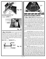
MOTOR INSTALLATION
❏
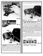
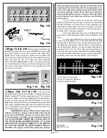
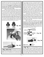
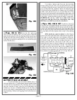
Figs. 153 & 154
BALL BEARING KITS do not
come with a motor bag. This means you will need to supply
your own motor, matching pinion gear, and capacitors.
These can be purchased from most local hobby dealers.
There is a chart in the tuning section of the manual that will
give you a recommended pinion gear for most motors. If you
have any questions, take your manual to your local dealer
and he can assist you. If you have any motor assembly or
installation questions, the following instructions for the bush-
ing versions will also work for the bearing kits as well.
BUSHING KITS contains a motor bag. This would be
inside the kit bag. Inside the motor bag you will find the kit
stock motor, the motor connector plug (with wire leads), three
.1uf (micro farad) capacitors and the bag containing the two
#6515 motor screws and two #6936 #4 aluminum flat wash-
ers.
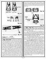
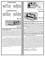
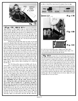
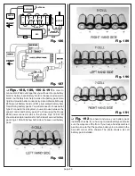
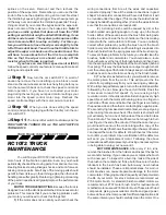
CAPACITORS We recommend the use of three .1uf
(micro farad) capacitors on all motors used in our bushing
kits. We supply three with the stock motor that comes in these
kits. For the ball bearing kits since you will be using an
electronic speed control, follow the speed control manufac-
turers directions for quantities, type and mounting locations
for the capacitors.
If the motor you purchased already has one or more
capacitors installed just add the ones you will need to bring
the total to three. Open the motor bag and remove the three
capacitors we supply. These will normally be a light brown or
blue color. Solder the capacitors on as shown in the drawings
in fig. 153. If your motor already has some installed just solder
on the ones that are missing according to the drawings.
Note:
Make sure that each lead of a capacitor only touches a lead
of another capacitor connected to the same terminal or can
grounding point.
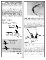
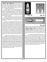
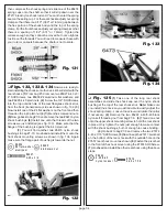
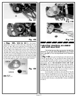
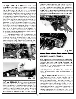
MOTOR CONNECTOR PLUG In the motor bag you
will find the motor connector plug. This has two three inch
wire leads coming out of the connector pins. Solder the end
of the red wire lead to the positive side of the motor. Then
solder the black or yellow wire lead to the negative side of the
motor. Make sure you are using ROSIN core solder to make
all electrical connections. If you have a ball bearing kit you
will not have a motor plug connector. Your speed
control may supply one, you can purchase what ever
style you like or you can hard wire. The choice is yours.


