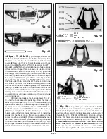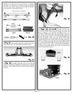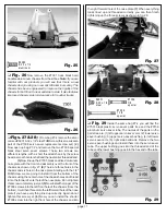
page 12
❏
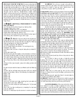
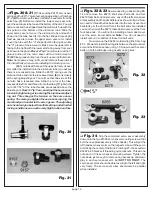
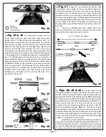
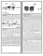
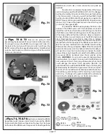
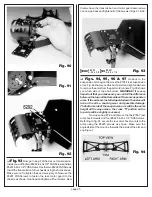
Figs. 30 & 31
(1) Take out the #9157 servo saver
spring and the #9157 aluminum spring adjusting nut from bag
#7-2.(2) Now remove the lower left servo saver arm from the
parts tree. (3) Before we install the lower servo saver arm
over the auminum tube, look at the bottom of the arm. You will
find a recessed hex shaped area that will match up with the
hex portion at the bottom of the aluminum tube. Slide the
lower servo saver arm over the alumnum tube and push it
down until the tube hex fits into the hex shaped recess. (4)
Next we need to remove the upper servo saver arm. Install
it over the tube with the "V" shaped portion facing down into
the "V" groove of the lower arm. Make sure the upper arm is
facing to the right (with the lower arm facing away from you)
as shown in the photo.
Racer’s Tip: Team drivers coat the V-
groove portion of the servo saver with a small amount of
#6588 black grease to improve the servo saver performance.
Note: Some servos may not fit, we will discuss these later in
the instructions when we are installing the steering servo.
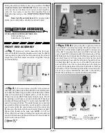
(5) If you look at the top of the upper left servo saver
arm (after it is installed onto the aluminum tube) you will see
there is a recessed area. Slide the #9157 spring over the
aluminum tube and into the recesssed area. (6) Look closely
at the spring adjusting nut. You will see that one side of this
nut also has a recessed area. Slide the nut over the tube,
recessed side first, and thread it onto the tube. (7)Tighten the
nut until 1/32" of the tube threads are exposed above the
adjusting nut.
Racer's Tip: You can adjust the servo saver
tension by tightening or loosening the aluminum adjust-
ing nut. This changes the tension on the servo saver
spring. The more you tighten the servo saver spring, the
more load you transfer to the servo gears. The adjusting
nut should only be below the initial setting under limited
racing conditions on an extremely high traction surface.
Fig. 30
Fig. 31
❏
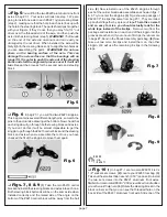
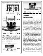
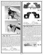
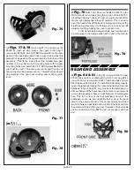
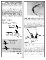
Figs. 32 & 33
Now we need to go back to bag #6-
14 and remove five #6270 short steel ball ends and four
#6272 foam ball end dust covers. Layout the left servo saver
arm assembly and the right bellcrank as shown in fig. 32. Now
we need to thread the five ball ends into the servo saver and
bellcrank per the photo. After all the ball ends are installed
you can then push the #6272 foam dust covers over the front
four ball ends. You will not be installing a foam dust cover
over the servo tie rod ball end.
Note: You do not need to
install nuts on the bottom of these five ball ends.
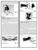
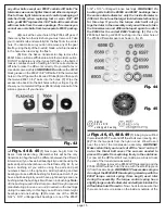
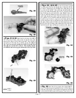
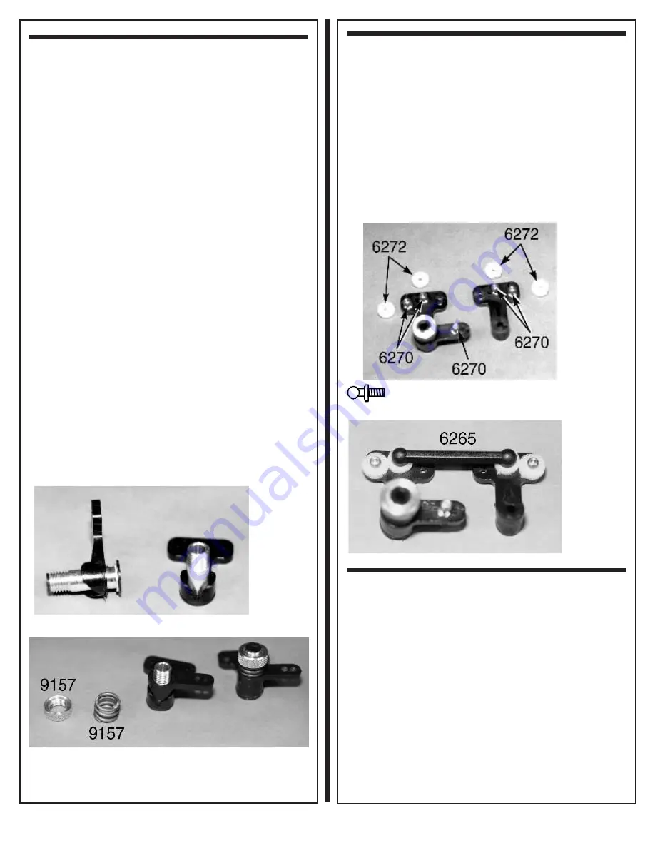
Now remove the #6265 molded drag link from bag
#7-2. We want to install the drag link between the servo saver
arm and bellcrank as shown in fig. 33. Snap it over the center
balls on both bellcranks using needle nose pliers.
Fig. 32
#627 0
4-40
Fig. 33
❏
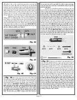
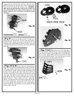
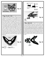
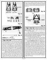
Fig. 34
Slip the completed servo saver assembly
down onto the two #7306 servo saver mounting screws (that
bolt the nose plate assembly to the chassis). This will put the
left hand servo saver arm on the longest screw with the servo
arm facing the center of the truck. From bag #7-2 take out two
#6222 4-40 black self threading nylon locknuts. Thread one
onto each of the servo saver mounting screws. Tighten the
nuts down just enough to remove any excess up and down
play in each servo saver arm, but NOT TOO TIGHT. The
servo saver arms should be able to swing to the left and right
very freely. The servo saver arms should also be parallel
when installed.


