

page 33
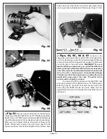
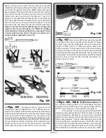
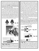
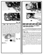
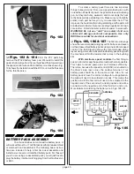
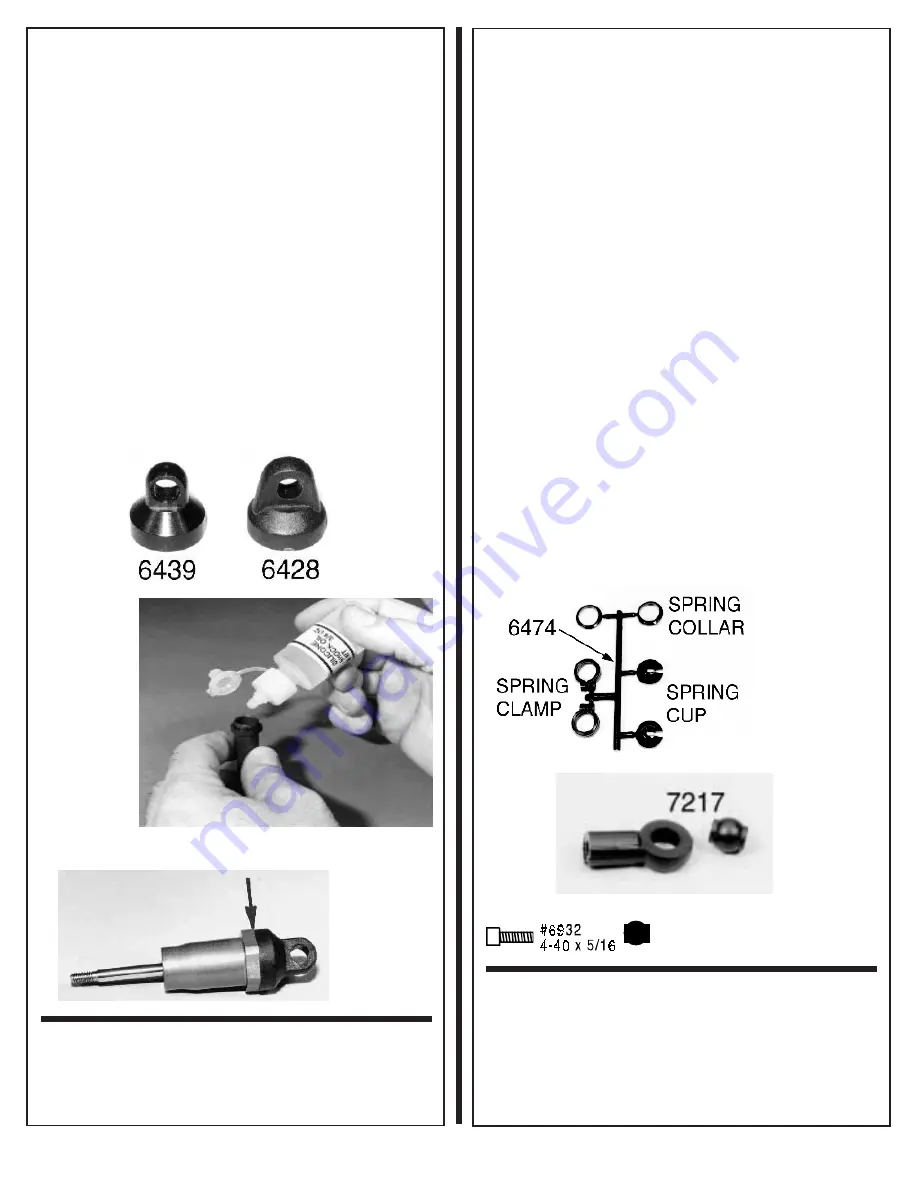
gap between the cap and the hex portion of the shock body
(see arrow in fig. 128). The O-ring will actually be doing the
sealing, so we must be careful not to overtighten the cap. As
soon as the cap comes in contact with the body just turn a little
bit further to seat it.
WARNING!!: not oiling the threads on
the plastic shock caps can cause them to seize onto the
shock body. You will not be able to remove the caps
when you go to service your shocks.
(5)Now work the shock shaft up and down about five
or six times, then push the shaft all the way in and let go of the
shaft. We want the shaft to come back out of the shock body
1/4" on its own. If it did not, pull the shaft all the way down then
unscrew the shock cap. Adjust the piston height inside the
shock body before you screw the cap on again according to
the following: If there was too much rebound (the shaft came
out too far on its own) then bring the piston closer to the top
of the shock body before you screw the cap on this time. If
there was not enough rebound then you will need to leave the
shock piston lower in the shock body before screwing the cap
on. If you have to make adjustments always recheck the oil
level before you make those adjustments. You are trying the
make sure all four shocks have the same rebound.
Fig. 126
Fig. 127
Fig. 128
❏
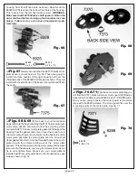
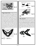
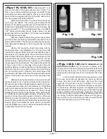
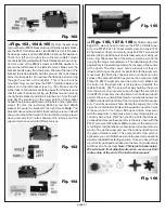
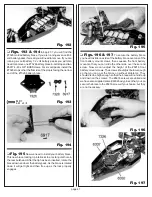
Figs. 129 & 130
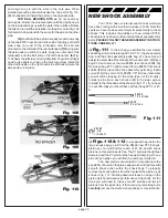
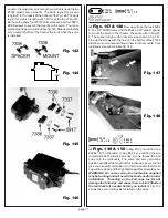
(1) From bag #7-11 remove the
two new #6474 spring clamps and cups parts trees and four
#6932 4-40 x 5/16" SHCScrews. Fig. 129 shows one of the
#6474 parts trees and identifies the three parts. (2) Now go
back to bags #7-9 and #7-10. Inside each bag there is a
smaller hardware bag. Remove two #7217 shock rod ends
and #7217 black plastic pivot ball ends (from each bag). (3)
Remove the shock spring clamp, spring collar, and spring
cup parts from the parts trees. (4) Slide the nylon spring
clamp onto each shock. To make it easier to adjust the
springs later, install the spring clamps so that the #6932
screws will be on the outside and facing forward on each
shock.(5) Each spring clamp has one open hole and one
closed hole for the tension screw. Install the #6932 screw
through each open hole and then thread it into the closed
hole. (6) Now slide the collar to the top of the shock body and
tighten it just enough to keep the collar from moving.
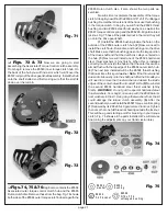
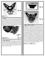
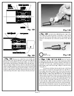
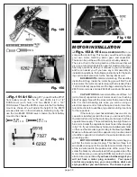
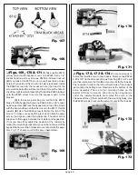
(7) Now take one of the #7217 shock rod ends and
push it into the plastic pivot ball. The easiest way to do this is
to place the ball end on a table or bench, set the nylon eyelet
over the ball and push down on the ball with your 1/4" nut
driver. You can also use needlenose pliers to squeeze the
parts together; just take your time and use the smooth part of
the jaws so you do not damage the plastic ball. Go ahead and
do the other three ball ends.
(8) Now thread the nylon shock rod end onto the
shock shaft. To keep the shock shaft from turning, you will
have to hold the shaft with your needle nose pliers.
WARN-
ING! Make sure you only grab the shaft with the smooth
part of the jaws of your needlenose pliers and as close
to the threaded end as possible. This is very important, for
we do not want to scratch the shaft where it will ride in the O-
rings, damaging the O-rings and causing the shock to leak.
Do the same for the other three shocks.
Fig. 129
Fig. 130
# 721 7
p iv ot ba ll
p la stic
❏
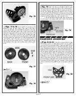
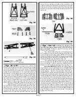
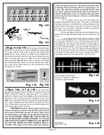
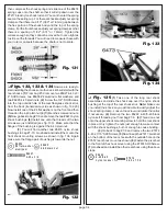
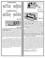
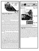
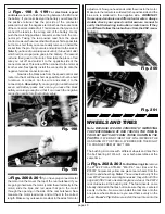
Fig. 131
Remove the two long #6480 (2.75" length)
rear green springs and two short #7427 (2.25" length) front
green springs from bag #7-11. Install one #6474 spring collar
onto each of the long rear green springs. Do the same for the
short front green springs. Slide the long springs onto the long
rear shocks. Next slide the short front springs onto the short
front shocks. Make sure the shock shaft is fully extended