page 28
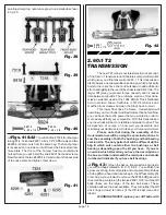
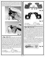
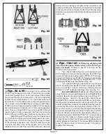
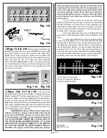
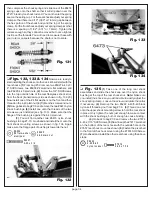
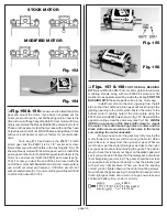
spacer. Line up the pin holes in the arm and hub carrier. (4)
Install the outer hinge pin through the forward pin hole of the
A-arm then through the hub carrier. (5) Now place the nylon
spacer between the hub carrier and the rear arm pin hole and
push the pin through the spacer and rear arm pin hole. (6)
Install one E-clip on each end of the hinge pin. Your com-
pleted rear arm assembly will look like fig. 105. (7) Now go
back and repeat the steps to assemble the right suspension
arm and hub carrier, making sure that the spacer is on the
rear side of the hub carrier just like the left arm assembly.
Racer’s Tip: The 1/8" spacer will allow you to change the
length of the truck's wheelbase for different handling
characteristics or track conditions, by moving it in front
or behind the rear hub carrier.The rear arm mount is no
longer position adjustable on the T2.
#62 99
e-c lip
1/8 sh aft
# 646 6
sp ac e r
1/8
Fig. 104
Fig. 105
❏
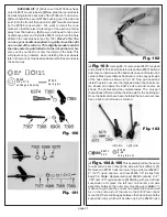
Figs. 106
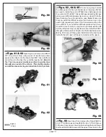
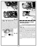
This step will also be the same for all
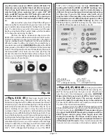
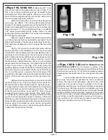
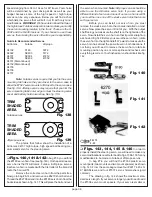
models. (1) Take four #6280 8-32 x 1/2" FHMScrews from
bag #7-8. We will start with the left suspension arm assembly
and line up the rear suspension mount over the two mounting
holes on the left side of the chassis. The only holes on the
mount that will line up with be the forward and the rear hole.
On this truck the inside holes cannot be used. Thread the two
screws into the mount from the bottom of the chassis. Now go
ahead and do the same for the right side arm assembly.
Remember the shock mounts will be on the front side.
# 62 80
8 -3 2 x 1 /2
a lu minu m
Fig. 106
❏
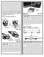
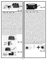
Fig. 107
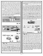
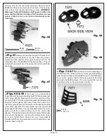
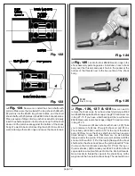
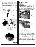
Remove four #6274 ball cups from bag #6-
14 and two #7253 truck turnbuckles from bag #7-8. Thread
the ball cups onto the turnbuckles evenly and adjust the
length to 3 3/64" (3.05" or 77.45mm) center to center of the
ball cup sockets. Then compare them to the scale drawing
shown at the bottom of the photo. On these two turnbuckles
the ball cups will face opposite directions. Just as on the other
turnbuckles, one end of the turnbuckle has right hand threads
and the other end has left hand threads. Remember the
photos are not to scale.
3.05”
#6274
#6274
#7253
Fig. 107
❏
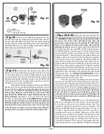
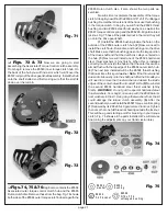
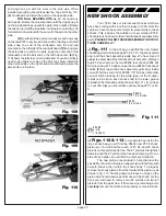
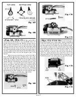
Figs. 108, 109 & 110
FOR BUSHING KITS
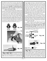
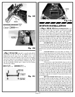
we need to remove two #6372 1/16" thick plastic dog bone
spacers and two #6372 dog bone springs along with two
#7361 truck dog bones. These will all be in bag #7-8.
(1) Look at fig. 108, we are going to install one #6372
plastic dog bone spacer into each of the two sloted outdrives
of the transmission. (2) Next we are also going to install a
#6372 dog bone spring into the sloted end of each of the two
#6374 rear stub axles. There is a hole drilled into the axle that
the spring fits down into. (3) Take one of the #7361 truck dog
bones and line it up with the slotted outdrive of the transmis-
sion. Go ahead and slide the dog bone pin into the slots. (4)
Now rotate the rear stub axle until you can line up the outside

