page 37
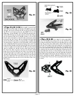
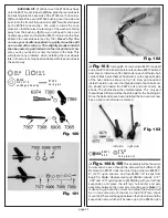
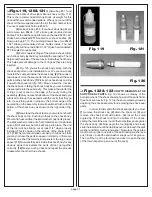
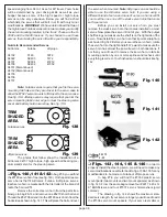
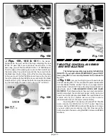
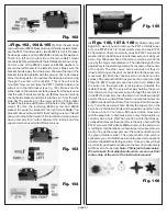
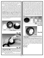
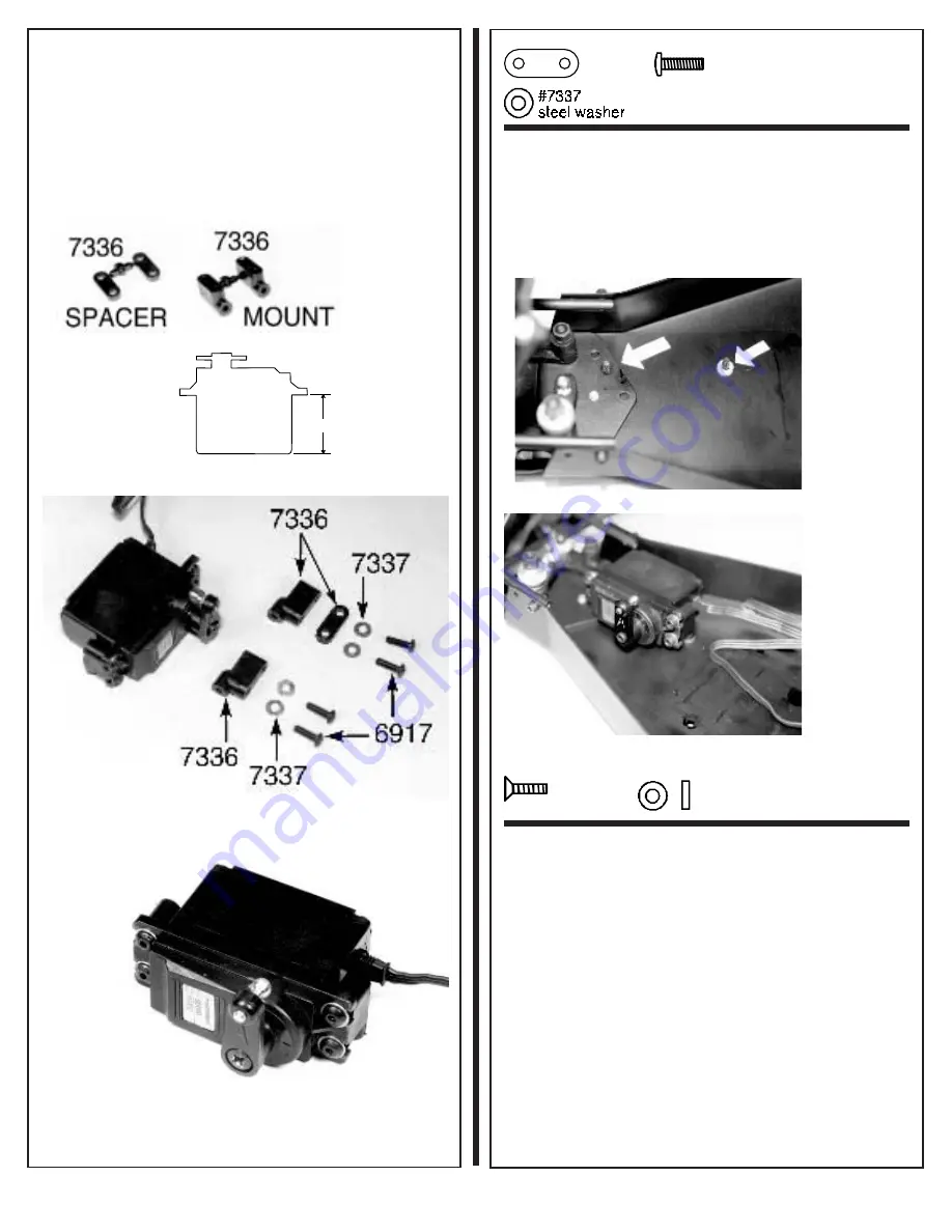
equal to the maximum servo length you will only need the two
#7336 plastic servo mounts. The parts layout for a servo
length of 1.40" or less is at the bottom of the fig. 145. The parts
layout for a servo length over 1.40" is at the top of fig. 145.
Both use the same four #7337 shim washers, and four #6917
BHSSscrews to secure the mounts to the servo. Your com-
pleted steering servo will look like fig. 146. Make sure that the
servo output shaft is to the back of the truck when the servo
is installed.
Fig. 143
1.40"
Fig. 144
Fig. 145
Fig. 146
#7336
spacer
# 69 17
4 -40 x 3 /8
❏
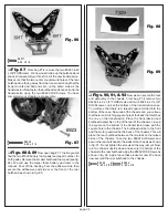
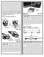
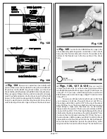
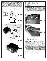
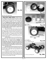
Figs. 147 & 148
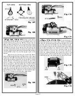
Now we will use the two #6292
4-40 x 3/8" FHMScrews and the #6466 1/16" plastic spacer
to mount the servo to the chassis. These are also in bag #7-
6. The spacer will go on the rear screw as shown in fig. 147.
Line up the screws with the holes on the bottom of the #7336
plastic servo mounts and thread them into the mounts. Your
installed servo will look like fig. 148.
Fig. 147
Fig. 148
#62 92
4-40 x 3 /8
#6 46 6
sp ac e r
1/16
❏
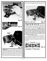
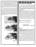
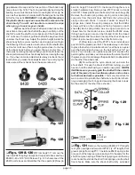
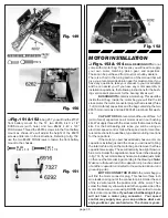
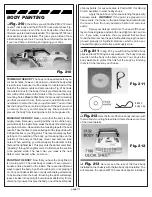
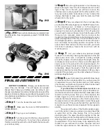
Figs. 149 & 150
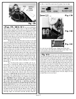
In bag #7-2 you will find one
#6262 1.65" turnbuckle. In bag #6-14 you will find the two
remaining #6274 plastic ball cups. Evenly thread the ball
cups onto the turnbuckle. The servo and servo mounting
position will affect the length of this turnbuckle so we cannot
give you a specific dimension. On this turnbuckle the left ball
cup will face down and the right ball cup will face towards you.
WARNING! For some servos the turnbuckle supplied
may be too long and will need to be shortened for proper
installation. Threading on the ball cups too far will
damage the ball cups and cause them to bind. Shorten
the turnbuckle if needed before you install it. Fig. 150
shows the servo turnbuckle installed on the truck.

