background image

FRONT MATTER 

CONTENT 

 PAGE 18 


9711-26020-0001 

Exp o rt  Co n tro lle d   – S e e   P a g e   3 

Rev B 

Figure 55.  ARMORUtils Wireless Devices Page


 ....................................................................................... 90

Figure 56.  Windows 7 Welcome Page


 ....................................................................................................... 93

Figure 57. Accessing Tablet PC Tutorials and Information


 ........................................................................ 94

Figure 58.  ARMORUtils Main Dialog Window


 ............................................................................................ 95

Figure 59.  ARMORUtils Backlight Setup Dialog


 ........................................................................................ 96

Figure 60.  ARMORUtils Wireless Devices Dialog


...................................................................................... 98

Figure 61. ARMORUtils Programmable Button Settings Dialog Window


 ................................................. 100

Figure 62.  Available Programmable Button Options


 ................................................................................ 101

Figure 63.  ARMORUtils Configuration Dialog


 .......................................................................................... 102

Figure 64.  ARMORUtils Battery Monitor Dialog


 ....................................................................................... 103

Figure 65. ARMORUtils Battery Information Window


 ............................................................................... 104

Figure 66. ARMORUtils Charger Control Settings Window


 ...................................................................... 105

Figure 67.  ARMORUtils Diagnostics Dialog


 ............................................................................................. 107

Figure 68.  ARMORUtils About Window


 ................................................................................................... 108

Figure 69.  Pen and Touch Utility – Pen Options Tab


 .............................................................................. 110

Figure 70.  Pen and Touch Utility – Flicks Tab


 ......................................................................................... 111

Figure 71.  Pen and Touch Utility – Handwriting Tab


 ............................................................................... 112

Figure 72.  Pen and Touch Utility – Touch Tab


 ........................................................................................ 113

Figure 73.  Touch Tab Virtual Mouse Pointer


 ........................................................................................... 114

Figure 74. Tablet PC Settings – Display Tab


 ............................................................................................ 115

Figure 75.  Tablet PC Settings Utility – Other Tab


 .................................................................................... 116

Figure 76. WACOM Pen Tablet Properties Window – Pen Tab


 ............................................................... 117

Figure 77. Settings and Options Supported by the ARMOR X10gx Active Pen


 ....................................... 118

Figure 78. Side Button Menu Options


 ....................................................................................................... 119

Figure 79.  Pen Tablet Properties - Advanced Settings Window


 .............................................................. 120

Figure 80.  Pen Tablet Properties – Pop-up Menu Tab


 ............................................................................ 121

Figure 81.  Pop-up Menu Add Options


 ..................................................................................................... 122

Figure 82.  Pen Tablet Properties Window – Calibrate Tab


 ..................................................................... 123

Figure 83. Tablet and Pen Settings Window – Settings Tab


 .................................................................... 124

Figure 84.  Tablet and Pen Settings Window – Display Tab


 .................................................................... 125

Figure 85.  Tablet and Pen Settings Panel – Pen Options Tab


 ................................................................ 126

Figure 86. Touch Settings Utility Window


 ................................................................................................. 127

Figure 87. Battery Positioned for Insertion


 ................................................................................................ 141

Figure 88.  Hard Drive Compartment


 ........................................................................................................ 143

Figure 89.  Memory Module Compartment


 ............................................................................................... 145

Figure 90.  Memory Module Ready for Removal


 ...................................................................................... 146

Figure 91.  ARMORUtils Diagnostics Page


 .............................................................................................. 153

Figure 92.  Armor Utilities Screen – Backlight Setup Dialog


 ..................................................................... 155

Figure 93. Tablet PC Settings Window


 ..................................................................................................... 157

Figure 94. Pen Tablet Properties Utility Window


 ...................................................................................... 160

Figure 95. Touch Settings Utility Window


 ................................................................................................. 162

Figure 96.  Intel Graphics Screen Rotation Options (from icon tray)


 ........................................................ 163

Figure 97.  Intel Graphics and Media Control Panel


 ................................................................................. 164

Figure 98.  Intel Graphics Panel Hot Key Manager


 .................................................................................. 165

Figure 99.  Low Battery Alert Message


 ..................................................................................................... 172

Figure 100.  ARMORUtils Battery Conditioning Window


 .......................................................................... 175

Figure 101.  Windows Battery Window Icon Examples


 ............................................................................ 176

Figure 102.  ARMORUtils Battery Monitor Page


....................................................................................... 177

Figure 103.  ARMOR X10gx Battery Label Example


 ................................................................................ 178


Tables 

Table 1.  Install the Battery Packs


 .............................................................................................................. 54

Table 2.  LED Indication Summary


 ............................................................................................................. 57

Table 3.  Configuring the External Antennas


 .............................................................................................. 63

Table 4.  Pen Screen Actions.


..................................................................................................................... 66

Summary of Contents for X10gx

Page 1: ...MODEL X10gx TABLET COMPUTER USER S GUIDE REVISION B Copyright 2010 DRS Tactical Systems Inc Melbourne Florida All Rights Reserved...

Page 2: ...0001 Export Controlled See Page 3 Rev B To learn more about ARMOR accessories please call 1 888 872 1100 PORT REPLICATOR RF DOCK BATTERY CHARGER DESK DOCK BREAKOUT BOX VEHICLE POWER SUPPLY UNIVERSAL D...

Page 3: ...ned by turning the equipment off and on the user is encouraged to try to correct the interference by one or more of the following measures Reorient or relocate the receiving antenna Increase the separ...

Page 4: ...rovide maximum shielding Equipment or its transmit antenna that is installed outdoors is subject to licensing Pour emp cher que cet appareil cause du brouillage au service faisant l objet d une licenc...

Page 5: ...FRONT MATTER CONTENT PAGE 5 9711 26020 0001 Export Controlled See Page 3 Rev B...

Page 6: ...ication This publication and any accompanying software may not in whole or in part be copied photocopied translated or reduced to any machine readable form without prior consent from the vendor manufa...

Page 7: ...FRONT MATTER CONTENT PAGE 7 9711 26020 0001 Export Controlled See Page 3 Rev B This Page Intentionally Left Blank...

Page 8: ...AZARDOUS AVERTISSEMENT RISQUE D EXPLOSION NE PAS D BRANCHER TANT QUE LE CIRCUIT EST SOUS TENSION MOINS QU IL NE S AGISSE D UN EMPLACEMENT NON DANGEREUX WARNING EXPLOSION HAZARD BATTERIES MUST ONLY BE...

Page 9: ...LOC regardless of the docking station used WARNING Changes or modifications not performed by or expressly authorized by DRS Tactical Systems Inc could be hazardous to your health could cause damage to...

Page 10: ...tery must only be carried out in a non hazardous area using the supplied AC adapter The definition of hazardous areas can be found in Standard EN 60079 10 CAUTION DO NOT use this unit in classified ar...

Page 11: ...ng 24 Data Storage 24 Dual Mode Display 24 Video Graphics 24 Wireless 25 WLAN Capability 25 Bluetooth Capability 25 Optional WWAN Capability 25 Optional GPS Capability 25 Audio 25 Batteries 25 Flexspa...

Page 12: ...Installing the Batteries 53 Turning On Your X10gx for the First Time 56 Turning the X10gx On Normally 56 Putting the Computer in Sleep Mode 56 Turning the Computer Off Normally 56 Emergency Shutdown 5...

Page 13: ...92 5 Your ARMOR X10GX Software 93 Getting Started with Windows 93 Windows 7 93 Windows XP 93 Help for Windows 94 ARMORUtils Program 95 ARMORUtils Main Dialog Window 95 Backlight Setup Dialog Window 9...

Page 14: ...123 Tablet and Pen Settings Utility Windows XP Only 124 Display Tab 125 Pen Options Tab 126 Touch Settings Utility Windows XP Only 127 6 Troubleshooting 129 Determine the Problem 129 Troubleshooting...

Page 15: ...creen Only 160 Using the Touch Settings Utility Windows XP 162 Rotating the Screen 163 Using the Intel Graphics Options 163 Using the Intel Graphics and Media Control Panel 163 Using a Keyboard Hot Ke...

Page 16: ...Purchase Replacement Batteries 178 How to Store Batteries When Not in Use 179 Short Term Storage 179 Long Term Storage 179 Battery Tips for Best Performance 179 Disposing Of Your Batteries 180 10DRS T...

Page 17: ...cy Vehicle Docks 50 Figure 28 X10gx Mounted in a Universal Dock with Keyboard Tray and Keyboard 51 Figure 29 ARMOR X10gx Battery Compartments 53 Figure 30 Battery Positioned for Insertion 54 Figure 31...

Page 18: ...gure 78 Side Button Menu Options 119 Figure 79 Pen Tablet Properties Advanced Settings Window 120 Figure 80 Pen Tablet Properties Pop up Menu Tab 121 Figure 81 Pop up Menu Add Options 122 Figure 82 Pe...

Page 19: ...ble Symptoms 129 Table 15 Remove and Replace the Solid State Drive 139 Table 16 Remove and Replace a Battery 140 Table 17 Installing a SIM Card 142 Table 18 Replacing a Memory Module 144 Table 19 Acce...

Page 20: ...ed for tools and without interrupting normal computer operations In addition you now have the functionality of both a touch screen and an active pen screen at your fingertips The ARMOR X10gx gives you...

Page 21: ...ase confirm that all of these items are present and in good condition NOTE Your hard drive is shipped already installed in the computer Contact your ARMOR X10gx Tablet Computer sales representative if...

Page 22: ...ations in this guide are relative to the front or face on view of the computer as it appears when it is set up for operation This guide can be viewed interactively on your X10gx using Adobe PDF Reader...

Page 23: ...at the time of its release However mistakes are possible and product updates may supersede the information in this guide We encourage you to contact DRS Technical Support toll free at 1 888 872 1100 w...

Page 24: ...erating systems in either 32 or 64 bit mode Processing The ARMOR X10gx is equipped with a 1 8 solid state drive SSD The standard solid state drive size is 32 GB but other sizes are available For infor...

Page 25: ...al positioning system GPS receiver This receiver uses GPS satellites to calculate its current location and elevation This information is then used by installed applications Optional GPS Capability Two...

Page 26: ...20 0001 Export Controlled See Page 3 Rev B The X10gx has additional space and flexible interfaces to allow the addition of custom cards and modules for extended capabilities Refer to Flexspace Flexspa...

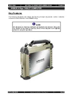
Page 27: ...agraphs and images describe the principal components controls indicators connectors and accessories of the ARMOR X10gx Key Features NOTE All references to front rear left right and top bottom location...

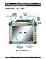
Page 28: ...Panel Features Figure 2 Front Panel Features CONTROL PANEL DUAL DISPLAY OR PEN SCREEN ONLY OPTIONAL GPS ANTENNA BEHIND COVER LED INDICATOR PANEL ACTIVE PEN WITH TETHER NOISE CANCELLING MICROPHONES 2...

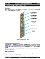
Page 29: ...n Refer to Programmable Buttons P1 P2 P3 Programmable Button Settings Dialog Window for information on how to select available options These buttons are also used to manually activate the battery fuel...

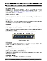
Page 30: ...dicators located on the indicator panel at the upper right of the X10gx display as shown in Indicators Figure 4 NOTE The seventh object to the far right of the panel is the ambient light sensor ALS no...

Page 31: ...antenna covers at the top of the computer see Speakers Figure 1 The speakers broadcast audible alerts generated by the operating system and application software and can be used to play back music or v...

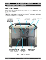
Page 32: ...Panel Features Figure 5 There is also a built in webcam a 50 pin docking connector and two RF docking connectors to connect external wireless and or GPS antennas Figure 5 Rear Panel Features DOCKING C...

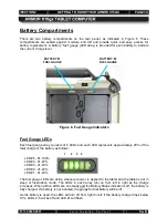
Page 33: ...nts approximately 20 of the total charge of the battery as follows Fuel Gauge LEDs LED 5 81 100 LED 4 61 80 LED 3 41 60 LED 2 21 40 LED 1 01 20 The fuel gauge LEDs are active whenever power is applied...

Page 34: ...Fuel Gauges You can activate the gauges for a period of 5 seconds by pressing any of the programmable buttons P1 P3 on the control panel The Flexspace compartment is a sealed compartment located at t...

Page 35: ...ure 8 A SIM card is a small electronic card that contains your subscriber ID billing information and network permissions The card allows you to easily transport your subscriber information to another...

Page 36: ...located in a sealed compartment on the lower left rear panel of the computer as shown in Memory Module Compartment Figure 9 NOTE When 4 GB modules become available the X10gx will support up to 8 GB o...

Page 37: ...n using the webcam to capture still and video images or for reading bar codes refer to Using the Webcam Figure 10 Built in Camera The X10gx can be connected to a number of docking stations including d...

Page 38: ...d with a DisplayPort cable connector A GB Ethernet port and two USB 2 0 ports are also located on this side of the tablet An AC adapter port is provided to connect an external power supply Left Side P...

Page 39: ...cover opens to reveal a compartment for three different types of removable digital cards There is a slot for a single PCI ExpressCard 34 54 or as a factory installed option a single Type I II PCMCIA c...

Page 40: ...0001 Export Controlled See Page 3 Rev B The bottom panel of the tablet has two docking station mount points and houses the Bluetooth antenna Bottom Panel Features Figure 14 Bottom Panel Features DOCKI...

Page 41: ...n batteries that are hot swappable That is if you have two batteries installed you can replace one battery while the tablet operates on the other battery With this capability you do not have to shut d...

Page 42: ...The digitizer detects the pen tip close to the screen and activates certain functions like steering the cursor or performing a right click action if the pen is allowed to hover for a few seconds Press...

Page 43: ...he batteries and can be used to power the unit A European power cord is available AC Adapter Figure 19 AC Adapter This microfiber cloth is specially designed to clean the display screen of dust and fi...

Page 44: ...ort The Flexspace compartment can provide up to 3 PCI e card slots 3 USB 2 0 ports 6 general purpose I O GPIO connections to the docking connector and 2 GPIO connections to the processor The antenna p...

Page 45: ...Each battery bay has a charging time of approximately 2 5 hours The external charger is also handy for recharging spare battery packs or batteries kept in storage Two Bay External Battery Charger Two...

Page 46: ...cator NOTE If you are using an ARMOR legacy docking station you must configure the BIOS to disable automatic power switching Refer to ARMOR Legacy Docks The desk dock Desk Dock Figure 22 holds the X10...

Page 47: ...F26200 0000 is equipped with two RF docking connectors to allow the X10gx to use an external wireless antenna and an external GPS antenna The non RF dock P N 9800F26200 1000 does not have the RF conne...

Page 48: ...10GX PAGE 48 9711 26020 0001 Export Controlled See Page 3 Rev B Figure 24 X10gx RF Dock and Breakout Box Figure 25 X10gx Vehicle Dock on a Ball Mount Assembly EXTERNAL ANTENNA DOCKING CONNECTORS BREAK...

Page 49: ...OUR ARMOR X10GX PAGE 49 9711 26020 0001 Export Controlled See Page 3 Rev B Figure 26 X10gx Docking Station Attached to Ball Mount Assembly BALL PLATE HORIZONTAL BALL PLATE VERTICAL OPTIONAL MOUNTING B...

Page 50: ...r these docks do not provide connections to external RF antennas The Universal dock can be equipped with a platform to support a compact keyboard and or joystick to make it easier to perform functions...

Page 51: ...t Controlled See Page 3 Rev B Figure 28 X10gx Mounted in a Universal Dock with Keyboard Tray and Keyboard For information on these and any other ARMOR X10gx accessories please contact your ARMOR sales...

Page 52: ...regulated voltage supply of 11 28 VDC 2 Voltages outside this range could cause unstable operation or result in permanent damage to the computer CAUTION Use only the external AC Adapter provided with...

Page 53: ...nstall and charge the batteries If you do not plan to use your computer immediately we recommend you store the batteries in a safe place until needed see How to Store Batteries When Not in Use The bat...

Page 54: ...e unit as shown in Figure 29 2 Press in and hold the button while sliding the latch down CAUTION Do not force the battery into position If the battery will not slip easily onto the connector pull it s...

Page 55: ...ond battery and press down until the connector seats 8 Slide the latch down until the button pops out 9 Connect the AC adapter to the AC adapter port on the left side of the tablet and allow the batte...

Page 56: ...s and release the Power button again to return to your session Putting the Computer in Sleep Mode When the computer is in sleep mode the screen will be dark but the status LEDs will still be active Th...

Page 57: ...that level Single LED off Power on Connected or Disconnected Installed Total charge is below this level Single LED off Power off Disconnected Installed No status LED 1 far left blinking at 1 second ra...

Page 58: ...IF THE INDICATION IS AND THE POWER MODE IS AND EXTERNAL POWER IS AND BATTERY IS THIS MEANS Steady red Power on Connected Removed A system error has occurred Drive Activity LED blue Flashing intermitt...

Page 59: ...e diagram in the center shows the approximate positions of satellites that are within range of the receiver The graph at the bottom of the page shows the relative signal strength of each satellite A g...

Page 60: ...ray The Realtek HD Audio Manager window opens with the Speakers main tab top of page open and the Speaker Configuration sub tab displayed as shown in Adjust your speaker headset volumes as desired Sel...

Page 61: ...phone main tab at the top of the page The Microphone main tab opens with the Microphone Effects sub tab displayed as shown in Microphones Figure 32 Set up and adjust your microphones Click on the Defa...

Page 62: ...ck sense pin that tells the X10gx when it is docked This allows the X10gx to turn off power to the docking pins when the tablet is undocked and turn power back on when it is docked Automatic Power Swi...

Page 63: ...ble button to enable or disable the antenna configuration that is selected in the Dock RF Mux panel NOTE If you have an X10gx RF dock installed but are not using external antennas you must set the Doc...

Page 64: ...s Docking Stations If you are using a legacy docking station whether it be a desk dock vehicle dock or port replicator power must always be available at the tablet docking connector pins so the automa...

Page 65: ...kly change back to touch screen mode This switching action is completely automatic and you will not notice any effects from it Currently the option to operate in touch screen only mode or pen screen o...

Page 66: ...the object or option Hover over object or option Move an object on the desktop Touch an object and move it with the pen Start an application or open a folder Tap twice Highlight option open menu opti...

Page 67: ...lus Actions MOUSE OBJECTIVE STYLUS ACTION Select tabs or open sub menus Highlight a label or option Fill selection boxes Activate buttons Deselect highlighted objects or release multiple objects Tap o...

Page 68: ...e the touch screen since the calibration routine will detect the active pen tip and not allow you to proceed Use your fingertip or a passive stylus designed for touch screens After a period of normal...

Page 69: ...Input Panel Touch the edge of the input panel to fully open it on the desktop as shown in Figure 35 The input panel has two modes handwriting and keyboard entry These are selectable by the two mode ic...

Page 70: ...ick on the Tools menu for handwriting options and for information on how to set up and use Input Panel When you tap on an open text document such as a WordPad document a keyboard icon will appear on t...

Page 71: ...ite the Input Panel expands to accommodate more text as needed If you want to convert ink to text the Input Panel does so dynamically Figure 38 Writing Pad Mode Pressing the middle button opens the Ch...

Page 72: ...creen Keyboard Mode You can customize the Input Panel based on your personal preferences such as automatic text insertion changing the ink thickness and adjusting the amount of space between lines in...

Page 73: ...3 icon on the desktop to open the Picasa application window as shown in Figure 40 2 Click on the Capture photos or video button in the options bar A Capture dialog window will open displaying the curr...

Page 74: ...SECTION 3 GETTING STARTED PAGE 74 9711 26020 0001 Export Controlled See Page 3 Rev B Figure 41 Picasa Application Window CAPTURE BUTTON...

Page 75: ...EAN 13 and ISBN shows a sample of a linear barcode Follow the procedure in Table 7 to scan a linear barcode Figure 42 Sample Linear Barcode Table 7 Scan UPC 10 EAN 13 and ISBN Barcodes in Windows 7 ST...

Page 76: ...ure 44 Sample 2D Barcode Table 8 Scan Datamatrix and QR Format Barcodes in Windows 7 STEP ACTION 1 Double click on the QuickMark icon on the desktop to open the QuickMark application window as shown i...

Page 77: ...SECTION 3 GETTING STARTED PAGE 77 9711 26020 0001 Export Controlled See Page 3 Rev B Figure 45 QuickMark Barcode Scanner Application Window Figure 46 A Captured 2D Barcode...

Page 78: ...is called Virtual Magnifying Glass Screen Magnifier To start the application click on the Virtual Magnifying Glass icon on the desktop or select Start Programs Virtual Magnifying Glass Use the Scroll...

Page 79: ...ith the display facing the sun Do not store the computer in temperatures below 40 degrees C Do not pile tools or heavy objects on top of the computer Avoid severe impacts especially to the display Do...

Page 80: ...obi WWAN Radio Table 9 View and Manage Network Connections STEP ACTION CONDITION OR INDICATION 1 Select Start Control Panel Network and Internet Network and Sharing Center The window shown in Figure 4...

Page 81: ...11 26020 0001 Export Controlled See Page 3 Rev B STEP ACTION CONDITION OR INDICATION 4 For more detailed information on the options and settings for these windows click on the Help icon Figure 48 Wind...

Page 82: ...SECTION 4 NETWORKING PAGE 82 9711 26020 0001 Export Controlled See Page 3 Rev B Figure 49 Currently Connected and Available Wi Fi Networks...

Page 83: ...nters A window opens Figure 49 showing any peripherals connected or available including cabled devices 2 Right click on the icon for your computer and select Bluetooth settings from the menu The Bluet...

Page 84: ...SECTION 4 NETWORKING PAGE 84 9711 26020 0001 Export Controlled See Page 3 Rev B Figure 50 Devices and Printers Window...

Page 85: ...SECTION 4 NETWORKING PAGE 85 9711 26020 0001 Export Controlled See Page 3 Rev B Figure 51 Bluetooth Settings Window...

Page 86: ...ualified technician in a controlled environment CAUTION Circuit boards containing electrostatic discharge ESD sensitive devices are exposed in this compartment Static free handling and processing is r...

Page 87: ...cradle out of the way to expose the SIM card socket 5 Place a fingertip in the notch on the left side of the socket cover and slide the cover to the right until you feel an indent then lift up 6 Inse...

Page 88: ...r The Sierra OneClick Internet Connection Manager window opens as shown in Figure 52 2 Select Settings and then click on the General tab The Settings window opens as shown in Figure 53 3 Select the de...

Page 89: ...SECTION 4 NETWORKING PAGE 89 9711 26020 0001 Export Controlled See Page 3 Rev B Figure 53 Sierra OneClick Connection Manager Window Figure 54 OneClick Connection Manager Settings Window...

Page 90: ...s will open the Wireless Devices page as shown in of your wireless radios at one time but keep working on your computer as when travelling on an aircraft Figure 54 Figure 55 ARMORUtils Wireless Device...

Page 91: ...difficulty connecting to your network try the following steps 1 Open the Wireless Devices dialog window in ARMORUtils and verify that the radio is enabled 2 If your tablet is not locked in a vehicle m...

Page 92: ...dure in Table 13 to connect to the LAN Table 13 Setting up a Physical LAN Connection STEP ACTION CONDITION OR INDICATION 1 You may need to contact your IT department or internet provider to access the...

Page 93: ...ove your configuration and control of the tablet and some may be custom software provided for your special requirements The following paragraphs provide you with an introduction to those software appl...

Page 94: ...opens as shown in Figure 56 Follow the instructions on the screen to access the tutorials Figure 57 Acces s ing Tablet PC Tutorials and Information For information on using Microsoft Windows features...

Page 95: ...nd much more ARMORUtils Program NOTE The screen images in this section are used for reference only and may not reflect the actual configuration of your X10gx To open the ARMORUtils main window double...

Page 96: ...01 Export Controlled See Page 3 Rev B The Backlight Setup dialog window allows you to adjust the screen brightness manually or automatically from a minimum of 5 to a maximum of 100 Backlight Setup Dia...

Page 97: ...eyes react differently to changes in light levels and there may be times when the full range of automatic brightness adjustment is uncomfortable for you Automatic Mode Profiles You can tailor the aut...

Page 98: ...RMOR X10gx all installed radios are enabled default condition Each radio can then be disabled by pressing its OFF button and re enabled by pressing its ON button Radio ON OFF Buttons There are RF dock...

Page 99: ...the computer unless you save your settings using the Save Settings button Save Settings Button Once you configure each radio and the RF switch to suit the way you normally use them ON or OFF you can...

Page 100: ...activate an additional function for P1 P3 by pressing and releasing the Fn button and then pressing and releasing one of the programmable buttons Fn P1 P2 P3 This provides a total of 6 preset functio...

Reviews: