Instruction manual
–
AQ F3x0 Feeder protection IED
83 (162
)
R
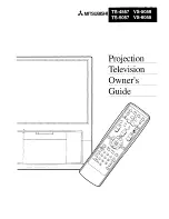
Load Angle
jX
Zone Z
Zone ZRev
-R Load
R Load
Note: For Zone 1:
Zone 1 ZRev=0
Figure 3-44: The MHO characteristics of the distance protection function on the complex
plane
If a measured impedance point is inside the MHO circle, the algorithm generates the true value
of the related output binary signal.
The procedure is processed for each line-to-ground loop and for each line-to-line loop. Then
this is repeated for all five impedance stages. The result is the setting of 6 x 5 status
variables, which indicate that the calculated impedance is within the processed MHO circle,
meaning that the impedance stage has started.
Polygon and MHO characteristics logic
The calculated impedance values are compared one by one with the setting values of the
corresponding characteristics. This procedure is shown schematically in figures below.
The procedure is processed for each line-to-ground loop and for each line-to-line loop. Then
this is repeated for all five impedance stages. The result is the setting of 6 x 5 status
variables, which indicate that the calculated impedance is within the processed
characteristic, meaning that the impedance stage has started.