


Normally, the primary line-to-line voltage rating for VTs is 400 V...60 kV, while the secondary voltage
ratings are 100 V...210 V. Non-standard ratings can also be directly connected as the scaling settings
are flexible and have large ranges.
Example of VT scaling
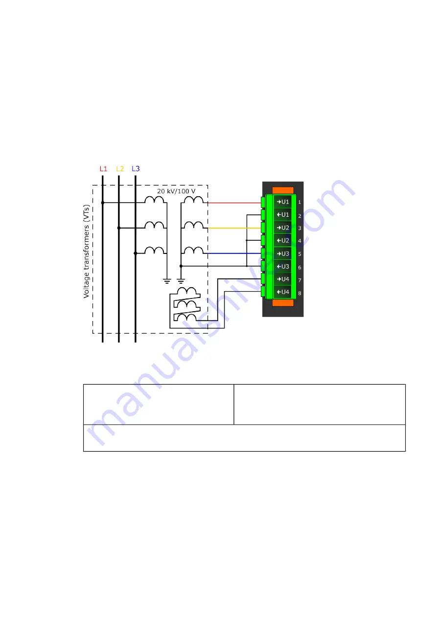
The following figure presents how VTs are connected to the relay's measurement inputs. It also shows
the VT ratings. In the figure below, three line-to-neutral voltages are connected along with the zero
sequence voltage; therefore, the 3LN+U4 mode must be selected and the U4 channel must be set as
U0. Other possible connections are presented later in this chapter.
Figure. 5.2.2 - 67. Connections.
The following table presents the initial data of the connection.
Table. 5.2.2 - 27. Initial data.
PPha
hase v
se volta
oltage V
ge VTT
- VT primary: 20 000 V
- VT secondary: 100 V
ZZer
ero sequence v
o sequence volta
oltage V
ge VTT
- U4 VT primary: 20 000 V
- U4 VT secondary: 100 V
- the zero sequence voltage is connected similarly to line-to-neutral voltages (+U0).
- in case wiring is incorrect, all polarities can be individually switched by 180 degrees in the relay.
If the protection is voltage-based, the supervised voltage can be based either on line-to-line voltages or
on line-to-earth voltages. This selection is defined in the "Measured magnitude" of each protection
stage menu separately (
Protection
→
Voltage
→
[protection stage menu]
→
INFO; see the image
below). The number of available protection functions depends on the relay type.
A
AQ
Q-F215
-F215
Instruction manual
Version: 2.04
72