


Figure. 7.1 - 254. AQ-F215 application example with function block diagram.
Protection functions
Device I/O
AQ-F215
Control functions
SOTF
Switch-on
-to-fault
SGS
1...8
0 → 1
79
OBJ
CLPU
Cold load
pick-up
∆V/∆a/∆f
25
DI
1...3
DO
5+1
CT
VT
4 voltage
channels
3 (IL)
2 (IL)
Add-on
3 slots
Monitoring functions
THD
31st
CTS
VTS
CBW
Circuit
breaker
wear
DR
Disturbance
recorder
21FL
Fault
locator
Current
-based
I>
50/51
(4)
I0>
50N/51N
(4)
CBFP
50BF
/52BF
(1)
I0d>
(1)
87N
Ih>
(4)
50H/51H
/68H
(4)
I2>
46/46R
/46L
TF>
49F
(1)
Voltage and
current-based
P<
(1)
32U
Pr
(1)
32R
P>
(1)
32O
Idir>
(4)
67
I0dir>
(4)
67N
I0Int>
(1)
67NT
U>
59
(4)
U<
27
(4)
U0>
59N
(4)
f>/<
81O/81U
(8)
df/dt >/<
81R
(1)
Voltage-based
U1/2>/<
47/27P
/59PN
(4)
∆α
78
(1)
Iv>
51V
(1)
Iarc>/I0arc>
50Arc/50NArc
OPTIONAL
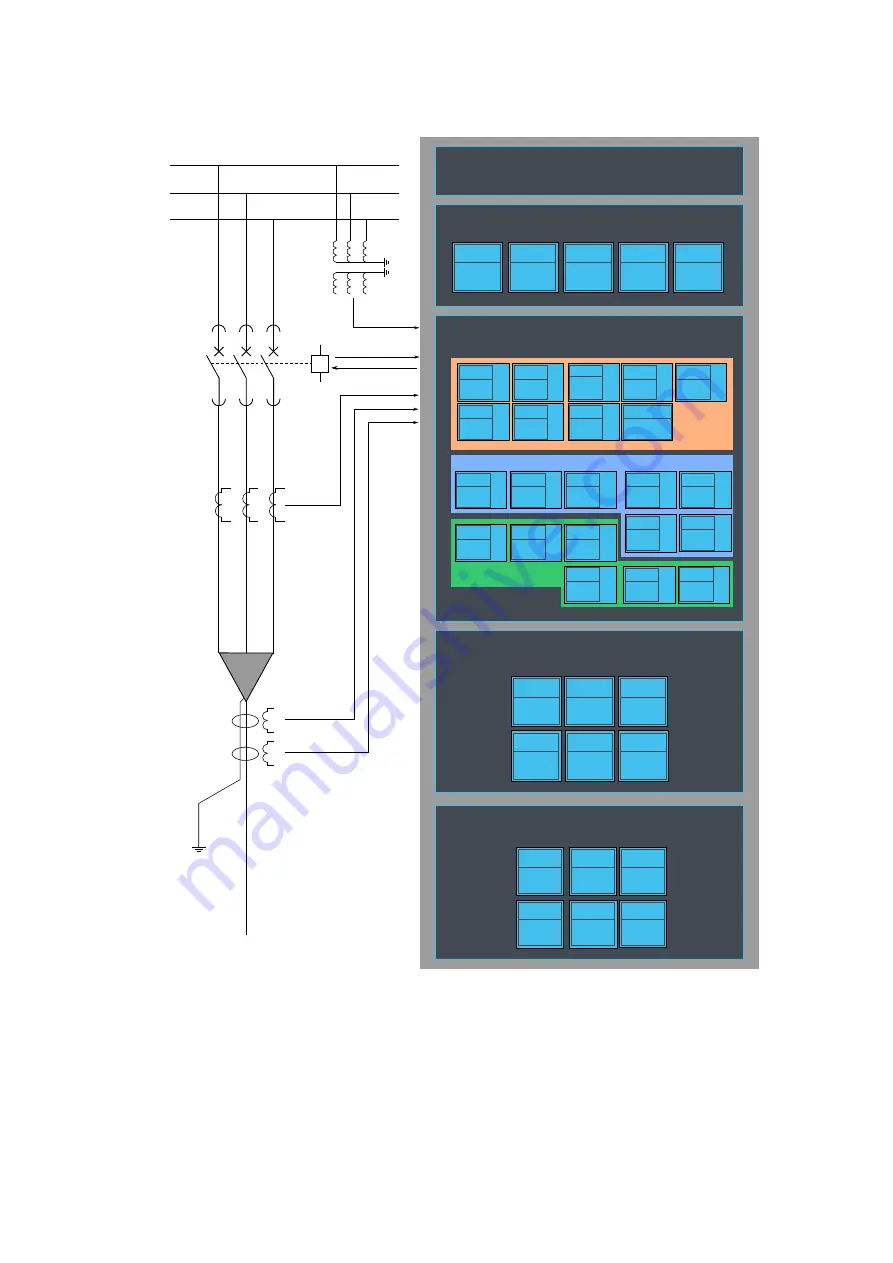
7.2 Application example and its connections
This chapter presents an application example for the feeder protection IED.
Since three line-to-neutral voltages and the zero sequence voltage (U4) are connected, this application
uses the voltage measurement mode "3LN+U0" (see the image below). Additionally, the three phase
currents and the residual current (I01) are also connected. The digital inputs are connected to indicate
the breaker status, while the digital outputs are used for breaker control.
A
AQ
Q-F215
-F215
Instruction manual
Version: 2.04
423