• setting parameters
• measured and pre-processed current magnitudes.
The function's output signals can be used for direct I/O controlling and user logic programming. The
function generates general time-stamped ON/OFF events to the common event buffer from each of the
two (2) output signal. The time stamp resolution is 1 ms. The function also provides a resettable
cumulative counter for the TRIP, ALARM 1, ALARM 2, INHIBIT and BLOCKED events.
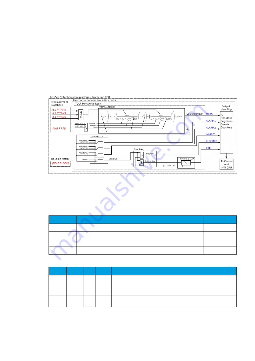
The following figure presents a simplified function block diagram of the line thermal overload
protection function.
Figure. 5.3.21 - 171. Simplified function block diagram of the TF> function.
Measured input
The function block uses analog phase current measurement values. The function block uses TRMS
values from the whole harmonic specter of 32 components.
Table. 5.3.21 - 170. Measurement inputs of the TF> function.
Signal
Description
Time base
IL1 TRMS
TRMS measurement of phase L1 (A) current
5ms
IL2 TRMS
TRMS measurement of phase L2 (B) current
5ms
IL3 TRMS
TRMS measurement of phase L3 (C) current
5ms
RTD
Temperature measurement for the ambient correction
5ms
Table. 5.3.21 - 171. General settings (not selectable under setting groups)
Name
Range
Step Default
Description
TF>
mode
0:
Disabled
1:
Activated
-
0:
Disabled
The selection of the function is activated or disabled in the configuration. By default
it is not in use.
Temp C
or F deg
0: C
1: F
-
0: C
The selection of whether the temperature values of the thermal image and RTD
compensation are shown in Celsius or in Fahrenheit.
A
AQ
Q-F215
-F215
Instruction manual
Version: 2.04
246


