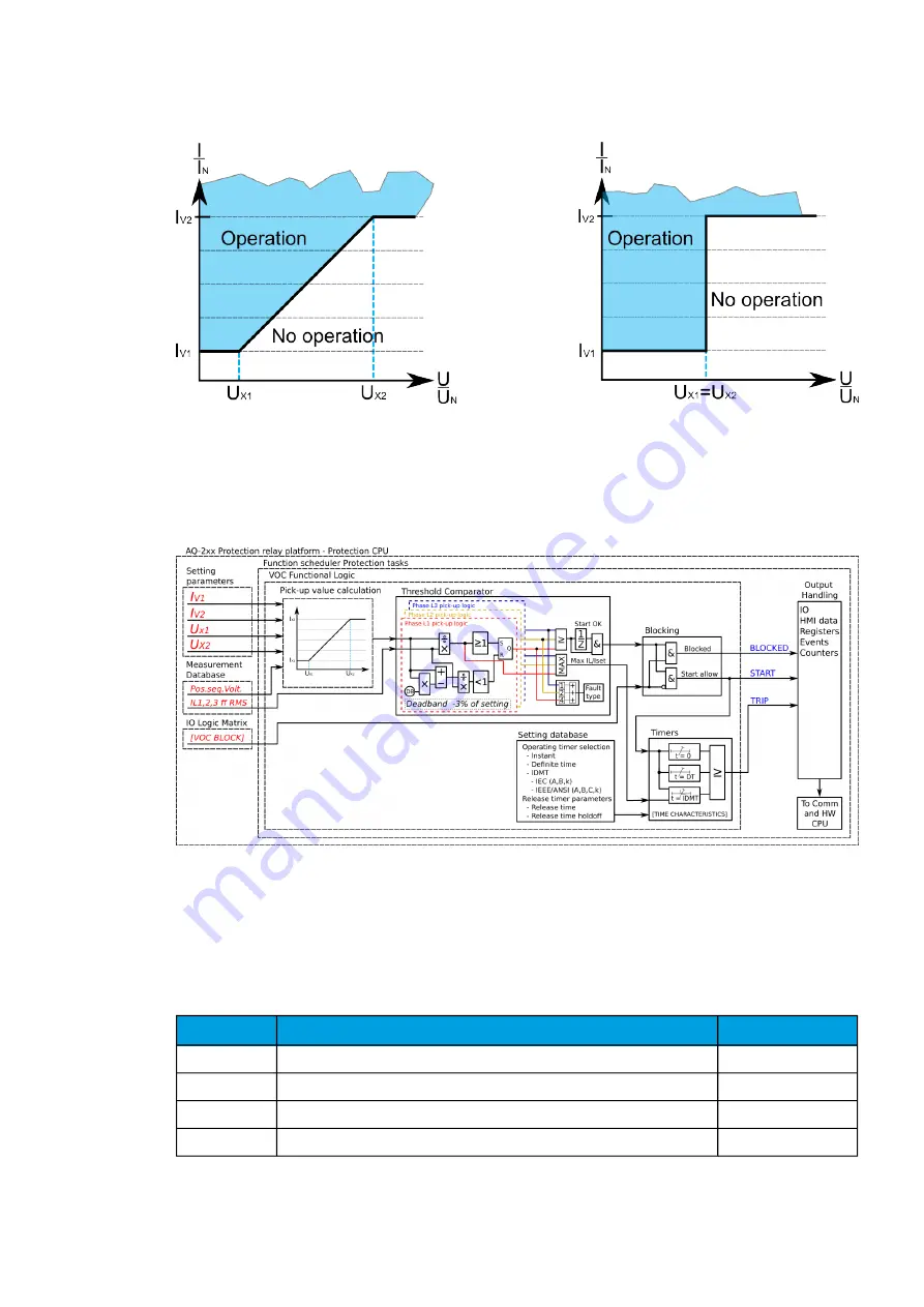
Figure. 5.3.20 - 157. Pick-up levels in the two modes.
Just like the other overcurrent protection functions, this function can be set to definite time (DT) or
inverse definite minimum time (IDMT) delay. However, if IDMT is selected for this function, the time
delay depends on the ratio between the measured current and the current pick-up level at
that moment. This means that the operation time can also shorten as a result of the reduced voltage.
Figure. 5.3.20 - 158. Simplified function block diagram of the Iv> function.
Measured input
The function block uses the calculated positive sequence voltage to determine the pick-up level.
Analog current measurement values are used to detect faults. A -20ms averaged value of the selected
magnitude is used for pre-fault data registering.
Table. 5.3.20 - 165. Measurement inputs of the voltage-restrained overcurrent protection function.
Signal
Description
Time base
IL1RMS
RMS measurement of phase L1 (A) current
5ms
IL2RMS
RMS measurement of phase L2 (B) current
5ms
IL3RMS
RMS measurement of phase L3 (C) current
5ms
U1
Positive sequence voltage
5ms
A
AQ
Q-F215
-F215
Instruction manual
Version: 2.04
229


