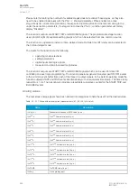
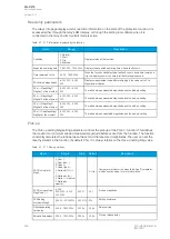

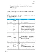
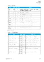
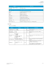


Name
Range
Step Default
Description
Power factor deadband
0.01…0.99
0.01
0.05
Determines the data reporting deadband settings for this
measurement.
Frequency deadband
0.01…1.00 Hz
0.01
Hz
0.1 Hz
Determines the data reporting deadband settings for this
measurement.
Current deadband
0.01…50.00 A
0.01
A
5 A
Determines the data reporting deadband settings for this
measurement.
Residual
current deadband
0.01…50.00 A
0.01
A
0.2 A
Determines the data reporting deadband settings for this
measurement.
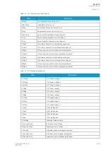
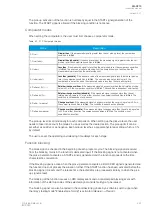
Voltage deadband
0.01…5000.00
V
0.01
V
200 V
Determines the data reporting deadband settings for this
measurement.
Residual
voltage deadband
0.01…5000.00
V
0.01
V
200 V
Determines the data reporting deadband settings for this
measurement.
Angle
measurement deadband 0.1…5.0 deg
0.1
deg
1 deg
Determines the data reporting deadband settings for this
measurement.
Integration time
0…10 000 ms
1 ms
0 ms
Determines the integration time of the protocol. If this
parameter is set to "0 ms", no integration time is in use.
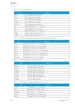
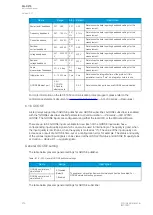
GOOSE Ethernet port
0: All
1: COM A
2: Double
ethernet card
-
0: All
Determines which ports can use GOOSE communication.
For more information on the IEC 61850 communication protocol support, please refer to the
conformance statement documents (
→
AQ-200 series
→
Resources).
6.1.6 GOOSE
Arcteq relays support both GOOSE publisher and GOOSE subscriber. GOOSE subscriber is enabled
with the "GOOSE subscriber enable" parameter at
Communication
→
Protocols
→
IEC 61850/
GOOSE. The GOOSE inputs are configured using either the local HMI or the AQtivate software.
There are up to 64 GOOSE inputs available for use. Each of the GOOSE inputs also has a
corresponding input quality signal which can also be used in internal logic. The quality is good, when
the input quality is low (that is, when the quality is marked as "0"). The value of the input quality can
increase as a result of a GOOSE time-out or a configuration error, for example. The status and quality
of the various logical input signals can be viewed at the
GOOSE IN status and GOOSE IN quality tabs
at
Control
→
Device I/O
→
Logical signals.
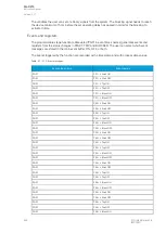
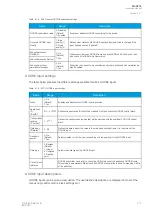
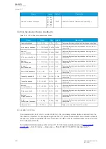
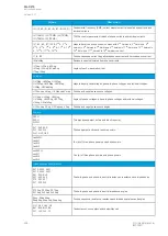
General GOOSE setting
The table below presents general settings for GOOSE publisher.
Table. 6.1.6 - 225. General GOOSE publisher settings.
Name
Range
Description
GOOSE control block 1
simulation bit
0: Disabled
(Default)
1: Enabled
The publisher will publish frames with simulation bit active if enabled. For
GOOSE simulation testing purposes.
GOOSE control block 2
simulation bit
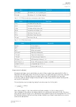
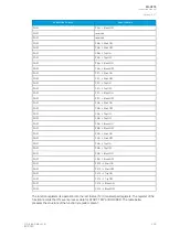
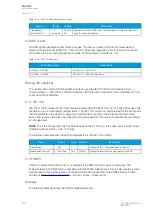
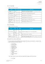
The table below presents general settings for GOOSE subscriber
A
AQ
Q-C215
-C215
Instruction manual
Version: 2.07
276
© Arcteq Relays Ltd
IM00040


